Wire drawing machines. Technological characteristics of the drawing shop. Technological process of the workshop
Drawing, by which wire products are produced, is a simple technological operation. Meanwhile, in order to obtain a high-quality product as a result of such a procedure, it must be carried out in the correct sequence and the appropriate equipment must be used for this.
Main stages
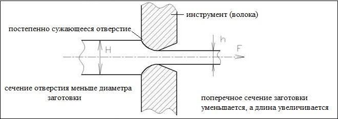
The essence of the technology by which wire drawing is performed is that a metal blank made of steel, copper or aluminum is pulled through a tapering hole - a die. The tool itself, in which such a hole is made, is called a draw; it is installed on special equipment for drawing wire. The diameter, cross-section and shape of the finished product are influenced by the parameters of the die.
Drawing, if we compare such a technological operation with rolling, allows us to obtain products characterized by higher surface cleanliness and exceptional accuracy of geometric parameters. Such products can be not only different types of wire (electrical, used for welding, knitting, etc.), but also shaped profiles, pipes and rods of different diameters. Products obtained using this technology are also distinguished by better mechanical characteristics, since during the process of drawing the metal, hardening is removed from its surface layer. As for wire production specifically, the drawing method can produce products whose diameter ranges from 1–2 microns to 10 or even more millimeters.
Drawing technology today is already well developed; for its implementation, modern models of drawing machines are used, operating without failures and allowing the technological process to be carried out at a speed of up to 60 meters of the finished product per second. The use of such equipment for drawing, in addition, allows for a significant reduction in the workpiece.

The production of wire using drawing technology includes several stages.
- The initial workpiece is subjected to an etching procedure, for which a sulfuric acid solution heated to 50 degrees is used. Scale is easily removed from the surface of metal that has undergone this procedure, thereby increasing the service life of the dies of drawing machines.
- To increase the plasticity of the workpiece being processed, and to bring its internal structure to a fine-grained state, preliminary annealing of the metal is performed.
- The remains of the etching solution, which is quite aggressive, are neutralized, after which the workpiece is washed.
- So that the end of the workpiece can be passed into the die, it is sharpened, for which a hammer or forging rolls can be used.
- After all preparatory operations are completed, the workpiece is passed through wire drawing dies, where the profile and dimensions of the finished product are formed.
- Wire production is completed by annealing. After drawing, the product is also subjected to a number of additional technological operations - cutting into pieces of the required length, removing ends, straightening, etc.
Features of the procedure
Any wire drawer knows such a drawback of drawing as an insufficiently high degree of deformation of the finished product. This is explained by the fact that when it leaves the processing zone of the drawing machine, it is deformed only to an extent limited by the strength of the end of the workpiece, to which the corresponding force is applied during processing.
The starting material that is processed on drawing machines is metal blanks obtained by continuous casting, pressing and rolling from carbon and alloy steels, as well as non-ferrous alloys. The drawing process is most difficult when a steel alloy is processed. In such cases, for high-quality drawing it is necessary to bring the microstructure of the metal to the required state. To obtain the optimal internal structure of steel, a technological operation such as patenting was previously used. This processing method consisted in the fact that the steel was first heated to the austenitization temperature, and then kept in molten lead or salt, heated to a temperature of about 500°.

The current level of development of the metallurgical industry, the technologies and equipment used in it for the production of metals and alloys make it possible not to prepare metal for drawing in such a complex and labor-intensive way. A steel billet leaving a modern metallurgical plant already has an internal structure that is optimally suited for drawing.
The drawing technology itself and the drawing equipment have also been improved over the years. As a result, the wire drawer today has the opportunity to use modern drawing devices, which make it possible to guarantee high-quality products with minimal labor costs. The quality and accuracy of processing performed on such specialized drawing machines is ensured not only by equipping them with modern working tools, but also by using a combined cooling system for their operation, which uses air and water. Coming out of such a drawing machine, the finished product has not only the required quality and accuracy of geometric parameters, but also an optimal microstructure.
What equipment is used to draw metals?
The equipment that a wire drawer uses in his professional activities is called a mill. A mandatory element of equipping a specialized drawing machine is the “eye” - the die. The diameter of the die, of course, should always be smaller than the cross-sectional dimensions of the workpiece pulled through it.

Today, manufacturing enterprises use specialized drawing machines of two main types, which differ from each other in the design of the pulling mechanism. So, they distinguish:
- machines in which the finished product is wound on a drum, which provides pulling force;
- equipment with linear movement of finished wire.

On devices of the second type, in particular, they perform drawing of pipes and other products that do not require winding on coils. It is wire, as well as small-diameter tubular products, that are produced mainly on machines equipped with a drum mechanism. Depending on the design, such machines can be:
- one-time;
- multiple, working with or without sliding, as well as those that use the principle of counter-tensioning of workpieces.

The single-shot drawing machine has the simplest design. By manipulating such equipment, the wire drawer draws the wire in one pass. On a multiple-type drawing device, which operates in a continuous circuit, the formation of the finished product is carried out in 2–3 passes. Large enterprises that produce wire on an industrial scale can be equipped with more than a dozen drawing machines of different capacities, on which products for various purposes are manufactured.
The main working body of any drawing machine, as mentioned above, is a die, for the manufacture of which hard metal-ceramic alloys are used - boron, molybdenum, titanium carbides, thermocorundum, etc. The distinctive characteristics of such materials are increased hardness, exceptional abrasion resistance, as well as low viscosity. In some cases, when it is necessary to make very thin wire from steel, the die can be made from industrial diamonds.

The die is installed in a strong and tough steel cage. This is the so-called drawing board. Due to its plasticity, such a holder does not exert significant pressure on the die and at the same time reduces the tensile stresses that arise in it.
In modern enterprises, metal drawing is often carried out using prefabricated dies, which allow this process to be carried out efficiently even under conditions of increased hydrodynamic friction. In addition, the use of such a tool reduces energy consumption and increases equipment productivity by 20–30%.
Preparation of metal blanks
A wire drawer, using specialized equipment, will only be able to achieve a high-quality final result if the surface of the workpiece is properly prepared. Such preparation consists of removing scale, for which the following methods can be used:
- mechanical;
- chemical;
- electrochemical.
A simpler and more cost-effective method is the mechanical descaling method, which is used for carbon steel workpieces. When performing such cleaning, the workpiece is simply bent in different directions, and then its surface is treated with metal brushes.

More complex and expensive is chemical descaling, which is performed using solutions of hydrochloric or sulfuric acid. A specialist performing such a complex and rather dangerous operation must be well prepared and strictly follow all safety rules for working with aggressive solutions. A chemical cleaning method is indispensable if the wire must be made from blanks made of stainless and other types of high-alloy steels. It should be borne in mind that immediately after chemical cleaning, the surface of the workpiece should be thoroughly rinsed with hot and then cold water.
The electrochemical method of descaling is based on the method of etching in an electrolytic solution. Depending on the implementation features, this method can be anodic or cathodic.
Copper wire drawing
To become more familiar with drawing technology, you can consider it using the example of how copper wire is made. Blanks for performing this operation are obtained by casting, after which they are alloyed together and rolled. In order for copper wire drawing to be carried out with the highest quality, it is necessary to remove the oxide film from the surface of the workpiece, for which it is treated with an acid solution.

The drawing process itself is not much different from the production of welding wire (or any other). In this case, the wire mill pulls the workpiece, passing it through die holes of a certain diameter. To produce copper wire of very small diameter (up to 10 microns), its formation can be carried out in a special lubricant composition (immersion method). In particular, the following can be used as such compositions:
- complex solutions;
- special emulsions;
- complex substances.
The use of such compositions, through which the wire passes during its formation, makes it possible to obtain products whose outer surface is characterized by maximum cleanliness.
0
Drawing is the process of deforming metal when pulling it through a hole whose output size is smaller than the original cross-section of the workpiece being processed.
Drawing is used to produce mainly thin wires with a diameter of up to 0.065 mm, as well as rods and thin-walled pipes of precise size. In some cases, profile assortment is finished by drawing.
Rolling produces wire with a diameter of at least 5 mm; To produce thinner varieties, they resort to drawing. Thin grades are not produced by rolling due to the rapid cooling of the metal.
The drawing process is schematically represented in Fig. 311, a.
In fig. 311, b shows three types of holes that can be made in the drawing board. The best is form A; it allows the drawn metal to gradually reduce its cross-section, and also reduces to a minimum the friction force that occurs during drawing.
Drawing holes, called eyes, dies, dies, can be made either in the drawing board itself, or in individual parts inserted into the board; in the latter case the board may be made of mild steel.
If the eyes are made in the boards themselves, the material used for them is high-carbon steel, chromium or chrome-tungsten, and special chromium cast iron.
Special steel, hard alloys, diamond, and agate are used as materials for insert eyes.
Thinning coefficient. The ratio of the diameter of the wire after passing through the drawing hole to its diameter before passing is called the thinning coefficient
![]()
here d1 is the diameter of the wire after drawing;
d is the diameter of the wire before drawing;
K is the thinning coefficient.
The smaller the value of K, the fewer passes through the drawing holes a wire of a given diameter can be obtained from the same source material. But the thinning coefficient cannot be reduced arbitrarily, since if its value goes beyond a certain minimum, the wire will break.
To determine the minimum value of the thinning coefficient, you need to clearly imagine the nature of the deformations experienced by the metal passing through the drawing hole.
The part of the wire located in the drawing hole is subjected to compression from the side of the hole cone; this pressure must be greater than the elastic limit of the wire material; the part of the wire located between the drawing board and the pulling mechanism experiences tension; the magnitude of the tensile force should not exceed the elastic limit of the wire material.

Let us denote by d the diameter of the wire before passing through the drawing hole and d 1 after passing through it (Fig. 312), z is the stress experienced by the wire in the stretched part, p is the pressure experienced by the wire from the side of the cone, y is the coefficient of friction between the wire materials and drawing board; then we get the following equality:
Since E,Fd is the lateral surface of the part of the cone in contact with the wire, then

When drawing mild steel wire, z = 20, p = 40 and y = 0.1 can be taken; then at a = 15°
![]()
For a stiffer material, the K value increases to 0.95.
Determination of the number of passes through drawing holes. Taking the value of K constant when drawing a certain type of wire, it is possible, based on the initial and final diameters of the wire and the value of K, to determine the number of passes of the wire through the drawing holes to obtain a given final diameter.
Denoting the diameters of the eyes through which the wire will be passed sequentially with the letters d 1, d 2 ..., d n, we have

The force required for drawing increases with decreasing thinning coefficient. The more the wire cross-section changes during the drawing process, the greater the force required for drawing; it can be determined by the formula

here k is the resistance of the material to deformation, taken equal to the arithmetic mean of its strength before and after drawing (the mechanical properties of the material after drawing change somewhat due to hardening);
F 1 - cross-sectional area of the wire after drawing;
F 0 - cross-sectional area of the wire before drawing;
y - friction coefficient;
a - angle of the drawing eye (see Fig. 312).
Power required for drawing, can be found from the equality

Drawing machines. Drawing machines are divided into machines with linear motion, or tongs, and machines with winding of the processed material, or block (drum).
Pincer machines are used for drawing thick short rods or pipes, block machines are used for drawing thin wire of arbitrary length.

The device of a pincer drawing machine is shown in Fig. 313, The movement of the roller chain and the pliers associated with it occurs in the direction indicated by the arrow. The pliers grab the pointed end of a rod or pipe passed through the drawing hole and drag it through the board. When the pliers reach the extreme right position, the hook that hooks the pliers to the chain jumps off the chain and the dragging stops. If you need to get a bar longer than the machine, the pliers move to the left end of the machine, and the bar is grabbed in a new place.
Work on such a machine proceeds slowly, with interruptions, so pincer machines are not used in the production of wire; they are used for drawing so-called calibrated iron and pipes.
The block stack device is shown in Fig. 314, a, b, c. The drum 1, on which the wire pulled through the drawing board 2 is wound, is mounted on a vertical shaft 3, the rotation of which is transmitted through bevel gears 4 and 5; lever 6 serves to lift the drum.

A chain with pliers is attached to the drum, capturing the pointed end of the wire passed through the drawing board. A cup of lubricant is placed in front of the drawing board, through which the wire is passed to facilitate drawing.
When drawing large-diameter wire, it is passed through a solution of sulfuric acid and copper sulfate in water (2-15 kg of sulfuric acid, 1-4 kg of copper sulfate per 70 kg of water). This, on the one hand, facilitates the work of drawing, since sulfuric acid somewhat corrodes the surface of the wire, and on the other, due to the fact that the copper fills the resulting irregularities, the wire receives a beautiful smooth surface.
There are also machines on which the wire is pulled through several holes at once. This method of drawing is called continuous.
Fig. 315 shows the structure of a continuous drawing machine having eight grooved blocks and the same number of drawing boards.

The wire from reel 1 passes through the eye of the drawing board and is wound onto the lower step of the drawing drum; Having made several turns around the step, it moves to the next (left), slightly larger stage of the drum, and from it enters the next smaller eye, etc. Having passed through the last smallest drawing hole, the wire enters receiving drum 2. Diameters of individual drums matched to the speeds of the gradually thinning wire.
During the drawing process, the wire is hardened and made brittle; To restore softness, it is annealed.
If the wire becomes excessively brittle during the drawing process, it is annealed between successive allowances through the drawing holes.
Pipe drawing can be done: 1) on a fixed mandrel; 2) on a mandrel moving with the pipe; 3) without mandrel.

Drawing on a stationary mandrel is shown schematically in Fig. 316, a; A diagram of the device for drawing pipes on a movable mandrel is shown in Fig. 316, b; 1 - a head with a conical hole into which dies 2 of various sizes are inserted (the size of the dies determines the size of the outer diameter of the prepared pipe); the end of the pipe is fixed in the drawing head 3, and the mandrel 5 is fixed in the head 4. The head of the mandrel 6 is fixed on the mandrel 5. Before starting work, the mandrel is moved to the left, the pipe with a slightly crimped end is passed through the drawing hole and secured in the drawing head; After this, the mandrel is pushed into the pipe. When the machine mechanism is set in motion, the pipe is drawn through the drawing hole, and it receives the dimensions determined by the dies and the mandrel head.
In fig. 316, c shows a mandrel moving with pipe 1, and securing the pipe to such a mandrel 2. To remove the mandrel from the pipe after crimping it, special devices are sometimes used.
Drawing without a mandrel is used in the manufacture of small diameters, pre-processed on machines with a mandrel. In this case, by preliminary drawing, pipes are made with a slightly larger diameter than the specified one and with a slightly smaller wall thickness; By passing through drawing holes, the pipe diameter is reduced and the pipe wall thickness is increased.
Drawing bimetallic wire is no different from ordinary wire drawing.
Download abstract: You do not have access to download files from our server.
For processing metal by drawing, machines are used, on which the drawing technology itself is carried out. With the help of this equipment, metal blanks are processed, which consists of pulling them through holes. The dimensions of these holes are significantly smaller than the dimensions of the workpieces, i.e. their sections. The workpieces are crimped; due to their crimping, their shape and cross-section change, which leads to an increase in their length. See fig. 1.
Metal processing This method for the production of parts with round and shaped sections has a number of positive characteristics:
- high profile accuracy;
- surface cleanliness.
And during production cold drawing method There are also additional advantages:
- increase in yield strength;
- strength;
- hardness of the drawn workpiece.
Many areas of industry and national economy widely use drawing products.
Drawing methods used:
- upon receipt of wire with a minimum diameter of 5 microns;
- for the production of thin pipes, pipes with a diameter of max. 400 mm.
Modern machines for processing metal parts by drawing are quite advanced. They are today:
- with increased productivity;
- good surface quality of the manufactured product;
- with increased die resistance;
- with improved safety conditions.
Good control and measuring technology makes it possible to accurately carry out drawing processes, which are already largely automated.
High tenacity dies enable significant increases in speed to be achieved and wire drawing beyond the fine diameter. Very stringent requirements are placed on the accuracy of wire diameter dimensions.
Devices of various designs are used to process workpieces by broaching. And there are two types of drawing machines.
Functional device The drawing device determines the purpose of the drawing mills. There are mills where the material is pulled in a straight line. This:
- chain,
- mills equipped with caterpillar traction,
- with reciprocating moving carriages,
- rack and pinion,
- hydraulic.
There are mills with a drum designed for winding the processed metal.
The purpose of mills with the movement of material being processed in a straight line:
- for drawing rods,
- pipe drawing,
- other products that are not wound into bundles.
Purpose of mills with winding material into coils:
- wire drawing with a special profile,
- drawing pipes with a minimum diameter.
They are characterized by the number of drums, the principle of their operation and are divided into:
- one-time;
- multiple, with sliding function;
- multiple, without sliding function;
- multiple, with reverse tension.
The name of single-pass drawing mills speaks for itself: the drawing process is performed in one pass. On multiple mills - in several passes.
Modern units for the production of steel wire by drawing are entire complex lines, which include equipment that ensures the execution of operations for the production of wire from various materials: low-carbon, high-carbon or alloy steels. The drawn material, which will be drawn, undergoes a series of technological preparatory operations or heat treatment. This is due to the future purpose of the wire.
The wire must be properly prepared for drawing. It must be pickled, maybe with a protective coating, subjected to hot and cold washing and drying.
After the above procedures for preparing for drawing, the wire is transferred to the drawing section of the production. Depending on the purpose of use, the wire after drawing is either heat-treated, oiled, tied or packaged. In case of partial use of wire by the same enterprise, it is transferred to the appropriate workshops or departments. It is transmitted on large reels or reels.
Auxiliary equipment
Each unit is equipped with main and auxiliary equipment. The main equipment performs the drawing operation.
Auxiliary equipment:
- unwinders,
- winders,
- devices for sharpening wire,
- lubrication equipment,
- packaging equipment for bundles,
- for cutting wire,
- for welding wire, etc.
One type of drawing mill, which we mentioned above, has a drum for winding the material. The number of passes during the drawing process and the type of mill do not change the basic equipment of the drawing mill. It includes: pulling drum, gearbox, electric motor.
Steel wire drawing equipment is different from non-ferrous wire drawing equipment. But the line between these types of equipment is blurring today. The process technology itself determines the specific requirements for the designs of drawing equipment and its main characteristics.
Drawing equipment can be either universal or standardized. In production areas with large capacities and a narrow assortment, specialized equipment is usually used, while in the production of a wide assortment it is advisable to use universal equipment.
Non-ferrous metal (copper, aluminum) has less strength than steel. This characteristic is the most decisive when choosing the main parameters of a drawing mill and its design.
For the process of drawing wire from soft materials, for example, non-ferrous metal, drawing machines with a sliding function are used. This is due to the fact that when sliding a wire made of a soft material, friction losses are less than when drawing a steel material. The increased ductility and lower strength of non-ferrous metal in any case makes it easier to fill the mill. In the production of steel wire, mills with a sliding function are used less frequently, mainly in the production of thin wire of minimum diameter and wire for special applications.
Single-pass drawing mills produce thick wire of various profiles and round sections, with a diameter of 25-40 mm, pipes made of ferrous and, to a greater extent, non-ferrous metals. When drawing large-diameter pipes, drums of also large diameter are used. The larger the diameter of the pipe, the larger the diameter of the drum chosen.
The workpieces are placed on the drum in only one row, which reduces the mass of the riot. The die moves along the drum, the material is wound without moving the turns along the drum. In this way, the surface and profile of the coils are protected from damage. Rice. 2 shows a mill with a moving die.
Single-shot drawing machines are designed for a force of 0.05-200 kN. This is determined by the characteristics of the material being drawn: cross-section, profile, quality. The drawing speed reaches 5 m/sec.
In single-shot mills, productivity increases due to an increase in the mass of revolts. This occurs both on the unwinding side of the source material and on the winding side of the finished wire. The larger the diameter of the wire being drawn, the greater the weight of the coils, which can be increased by welding.
A single drawing machine with all auxiliary components is shown in Fig. 3.
Gearbox 1, gearbox 2, electric motor 3, unwinding figure 4, sharpening device 5, lift 6 and rack 7.
Receiving devices are used to transfer the wire to subsequent operations. The mill stops only when the receiving devices are changed, which occurs at the moment it is filled. This is a fairly quick procedure. For coils with a large mass of up to 3 tons, special receiving devices are used. The sequentially fed coils are transferred to drawing without stopping the mill, without reducing its speed.
Motors on single-shot drawing mills can be of both direct and alternating current. They must ensure the operation of the mill at creeping speed, smooth start-up of the unit, jog operation, speed control during drawing, and the possibility of emergency stop.
2. Double drawing mills
Double drawing machines perform the drawing process in two passes, in other words, when two broaches are enough. This is necessary to ensure a given wire size or when production volumes are small. With two broaches, the material is subjected to fourfold compression.
The simplest version of such a mill is to use a two-stage drum. At the first stage, the drum has a smaller diameter, which ensures the sliding of the wire. Different wear of the rolls makes it possible to install the hood 1-2% higher than the hood due to the difference in the diameters of the steps.
Sliding occurs at the bottom step, otherwise the wire may break. There is no possibility to give high compressions here.
Differential double drawing machines operate on both stages without slipping, but allow high as well as low reductions. We see a differential mill operating on the principle of double drawing in Fig. 4. It has two drawing drums located on the same axis.
3. Multiple stuns
Multiple drawing mills are equipment in which the workpiece is drawn through several dies simultaneously. This is done in order to increase the extraction of the processed material. The dies are located one after another in series.
To determine the drawing ratio, the dimensions of the material being processed, its cross-section, the specified size of the final product and its mechanical properties are essential. Usually the multiplicity is set in the range of 2 - 25, but more can be set.
The stronger the material, the more difficult it is to stretch. There is not enough tension behind the last die to simultaneously pull the material through all the dies of the multiple line. For this purpose, a separate pulling drum is used after each drawing. The pulling drum rotates, the drawn material, leaving the die, is wound onto the drum, at the same time unwinding, and moves on to the next die.
Multiple mills with sliding function
There is a proportion or ratio for all dies of the multiple drawing mill.
This condition is the key to the successful operation of the unit:
F1v1 = F2v2 = ... = Fnvn,
in this case F1, F2, ..., Fn is the cross-sectional area of the wire when it leaves the die;
v1,v2, ..., vn - speed when winding the wire onto the drum, when the wire comes out of the die.
The volume of material that is pulled through one die in a certain time must be the same for all dies of the mill, otherwise the wire will tear, throw off loops, and then get tangled.
The multiple drawing line shown in Fig. 5a, consists of 7 dies (item 1), sequentially located one after another, and 7 drums (item 2 and 3). The wire for drawing is put on the figure (item 4) (not driven). All seven reels are pulling. Drive pos. 5 and gearbox pos. 6 drive each drum installed for each die for drawing wire.
Several turns of wire are wound onto each drum, position 2. In operating mode, each revolution of the drum corresponds to winding one turn. In this case, one turn is wound from above. This is how a constant number of turns on the drum is ensured. The drawn wire as a finished product is wound onto a drum pos. 3.
During the operation of the mill, its dies naturally wear out. There may be inaccuracies in the manufacture of dies. Both aspects can cause a discrepancy between the peripheral speed of the drums and the speed of movement when pulling the wire between the dies.
It may turn out that the pulling speed will be some value greater than the peripheral speed of the intermediate drum. The drum will not be able to produce pulling force. In this regard, on mills of this type, with a sliding function, the peripheral speed of the internal drums is chosen to be 2-4% higher than the speed of the wire when it leaves the die. Due to this difference in the relative speeds of the drums, except for the last drum, the wire slips. This determines the name of the drawing mill "sliding mill".
Repeated drawing machines with sliding function are suitable for wire drawing production of soft materials such as copper, aluminum and mild steel. Made from durable steel, the wire slips only slightly. Otherwise, if there is strong sliding, the wire will become very hot, and significant wear on the surface of the drum will occur. And the surface of the wire itself will become rough.
When producing thin wire (less than 0.5-0.1 mm in diameter), step mills are used. For an example of such a mill, see Fig. 6. The designs of such mills include max. four drawing spindles and a maximum of 25 dies. In this case, it is necessary to select the dimensions of the dies and the diameters of the drums in stages. We see the wire drawing speeds on today's multiple mills in the following table:
Twin Drum Mills
In multiple drawing mills, where wire accumulates and can begin to curl, new ideas have been developed and applied. These developments are aimed at a method for winding wire onto drums and transporting it to the next die.
Shown in Fig. 8 mill represents a structure made of blocks. The number of blocks is equal to the drawing ratio. This type of design differs from the designs of conventional mills in that the spindle is equipped with two drums. The drums are installed one above the other. The drum at the bottom is fixed to the spindle with a key. The upper drum rotates freely thanks to the rolling bearings on which it is mounted on the spindle.
The wire is guided by a roller from bottom to top. It is wound onto the drums in opposite directions. See Figure 9. The wire, accumulating on both drums, upper and lower, goes down the rollers (2 guide rollers) to the drag of the next block. The process is repeated in the same way as in the 1st block.
The ends mounted on the drums fix the maximum and minimum wire reserves on the drums. When the maximum supply is reached, the end is triggered and stops the drum. As soon as the wire supply is again minimal, the other end gives a signal to start the drum.
If the upper drum is at rest, the guide roller rotates slower than the lower drum (twice). This promotes equal accumulation of wire on both drums with the same diameters.
With a slower winding of wire from the upper drum compared to winding on the lower drum, the accumulation of wire on both drums increases, and the guide roller makes rotation around the spindle axis slower than the difference in speed of the two drums, exactly twice.
If the amount of wire removed from the upper drum is equal to the amount of wire that was formed as a result of winding on the lower drum, then the guide roller does not rotate around the spindle axis. When the amount of wire wound from the upper drum exceeds the amount formed as a result of winding on the lower drum, the wire accumulates more slowly. The roller begins to rotate in relation to the rotation of the lower drum in the opposite direction, and the speed of rotation of the roller is lower than the difference between the rotation speeds of the upper and lower drums (exactly twice).
The drums of these mills are equipped with individual drives. The design of these mills has, along with a number of advantages (the wire does not twist, the finished wire can be removed from the drum and the spools can be replaced without stopping the unit, any drum can be stopped separately, an AC drive can be used) its disadvantages, which consist in numerous bends of the wire. As a result, it is difficult to thread the mill when there is wire with a large cross-section, which is intended for the drawing process.
Mills with a different drum design work on the same principle of operation, when they are placed one inside the other. Mills that have a counter-tension function are considered improved.
Multiple counter-tensioning machines or loop machines.
Counter-tension helps reduce die wear and the wire becomes more uniform in thickness. This makes it possible to perform the drawing process at high speeds.
Counter-tension is created by adjusting the speed of rotation of the drums, thereby preventing the wire from sliding along the drum. Such mills are equipped in the same way as other multiple drawing mills: several drums located one behind the other and dies installed between the drums.
See fig. 10. The designs of the drums on such mills are similar to the designs of the drums of new mills equipped with a sliding function. Motors are frequency controlled. Adjusting the speed of the drums ensures continuous wire drawing without slipping.
The wire goes around the drum, heading towards the tension roller, then goes around the idle roller, which is motionless, moving towards the die. After leaving the die, the wire goes to the next drum, and the process repeats. We see the direction of the wire in Fig. 10. It is indicated by arrows.
1 — finishing drum block; 2 — intermediate drum block; 3 - buffer; 4 - tension roller; 5 — speed controller; 6, 8, 10 — soap dishes; 7 — stepped drum block; 9 — guide roller; 11 — fan; 12, 13 — under-engine plates; 14 — gear coupling; 15 — electrical blocking of the shield; 16 — drawing speed meter: 17 — plate under the blocks; 18 — electric motor; 19 — shield; 20 - oil drain; 21 - foot barrier; 22 - manual barrier
In Fig. 12 shows an intermediate drum.
The drum position 1 is mounted on the spindle position 2. Motor drive using a gear coupling, multi-start worm pos. 4 and the worm wheel pos. 3 sets the drum in motion. A separate block consists of a drum pos. 1, spindle pos. 2, gear housing, represented by the upper pos. 6 and lower pos. 5 parts of it. The number of passes during the drawing process determines the number of blocks subsequently mounted on the frame. Due to the fact that such drawing machines are high-speed, only a few turns are wound on the drums, the drum and wire heat up, and they need to be cooled. Water is supplied to cool the drums. The wire is cooled with air. The dies are mounted in a so-called soap box and cooled with water. The mill structure is shown in Fig. 13.
The emergency switch turns off the unit if the wire gets tangled. Mills equipped with a counter-tension function have a number of advantages:
- when transporting wire between drums, it does not twist;
- counter-tension is created by adjusting the speed of the drums automatically;
- the counter-tension function helps reduce wear on the dies and reduce heating of the wire; this improves the quality of the wire and ensures high-speed drawing;
- there is no need to remove the wire from above, which eliminates injury to operating personnel.
This design of loop drawing mills has a number of disadvantages:
- when producing wire from high-strength steel, it is difficult to feed the mill;
- a large number of rollers (tension rollers, guides) creates additional bends for the wire;
- counter tension is adjustable within a small range;
- the forced use of direct current leads to increased cost and complexity of this design.
These disadvantages are not inherent in straight-through mills with a counter-tension function.
Loopless mills (direct flow)
In Fig. 14 cm another mill design with counter-tension function.
On this unit, only a few turns are wound onto the drums (from 6 to 10 wire turns per drum). These turns are quite enough to create the necessary friction force concentrated between the drum and the wire. The strip is pulled through the dies without slipping. The wire is transported without rollers, which prevents the strip from twisting during the transition.
Counter tension on loopless mills is created by electric motors. This allows higher counter-tensions to be applied and adjusted over wider ranges. The fact that these mills do not have so many different rollers makes it easier to thread the mill when drawing thick wire from high-strength materials. Not all types of wire allow large crimps. It is for them that the use of countertension is important and effective. Shaped wire is produced using small crimps. This reduces wear on the dies.
When producing low and high carbon steel wires, the back tension used is max. 10-15% of the total drawing force. In Fig. Figure 14 shows a mill for the production of wire from high-carbon steel grades by drawing. The mill drums are equipped with an individual DC drive. The drums are connected in series.
The torque is adjusted so that its excess determines the amount of counter-tension. The speed is adjusted only on the finished wire drum, the other drums are adjusted automatically based on the rotation speed of the finished wire drum and the reductions used in each die.
When threading the mill, the motor adjustment continues until its torque is sufficient to pull the wire through the die and create tension to turn the drum (back tension). It reduces pressure on the walls, and thereby reduces friction and heating.
With less heat, you can set a high speed during the drawing process. Excessive heating destroys the lubricant and reduces the quality of the wire and its surface. In such units, water is supplied to the drums and dies for cooling purposes, and cooling air is supplied to the wire.
Cooling helps to reduce the heating temperature of the wire and increases its tensile strength.
Mills of this type have the following positive aspects:
- when drawing the wire does not twist,
- provides drawing of wires of various profiles and non-circular cross-sections,
- wide range of counter-tension adjustment,
- there is no difficulty in refueling the mill,
- no rollers - no unnecessary wire bends,
- no speed controller,
- simplified diagram of the unit (mechanical and electrical).
Perhaps, the use of low voltage DC electric motors (less than 110 V) is one of the significant disadvantages of this design of such mills.
In Fig. 16b demonstrates the following type of drive, which creates a differential transmission. It is located between the electric motor and the gear train. Setting the speed of the drums directly depends on changing the compression mode. The speed is adjusted automatically.
When changing the compression mode, it is necessary to change the gear ratio on all drums. This is done on all straight-through mills that are equipped with AC drives. And the drives can be both individual and group. Individual - each block has a separate drive, and group - this is when one common drive is installed on all blocks at once.
The rapid change of modes during the operation of such mills is an indicator of its productivity. And the faster the mill operators begin to acquire skills in operating and servicing the unit. By turning the handle of just one switch on a mill equipped with a DC drive, the operator switches all the drums to a different speed. AC drives are more complex for such a simple switching of drawing speeds; here it is associated with switching gears in all gearboxes and in gearboxes, or switching is undertaken in both control units at once.
And most importantly, on AC drives it is difficult to enable soft start or smooth acceleration, which is very important when switching speeds, especially in the direction of increasing it.
This problem can be improved through the use of hydrodynamic couplings, because they help to significantly reduce the dynamic loads on gears when changing modes, when starting or stopping the unit, and also reduce the likelihood of wire breakage due to switching from one operating mode of the mill to another.
Mills with an AC drive cost less in terms of money than mills with a DC drive. But the latter, i.e. DC drives are more convenient to maintain and control. They have a much larger speed control range on all reels, and when changing the compression mode, the speed is adjusted automatically.
4. Production lines for wire drawing
Multiple drawing mills are, as is known, production lines. This means that the process on the line goes on continuously, from the delivery of blanks to the receipt of the finished wire, without stopping the line. Such mills process wire, deforming it as much as possible, stretching it between heat treatments or immediately crimping it to a given size.
Using this technology, it is possible to combine several single drawing mills in one line. By combining units in this way that were previously located in different parts of the workshop, time is saved on the costs of operations and transportation of workpieces.
Production lines are assembled from similar equipment according to power data, otherwise the overall productivity of the newly equipped production line may drop.
Combination of mechanical descaling and drawing operations
Today there are many combined lines known. Just as units for removing scale from products mechanically are combined with pickling lines, today devices for removing scale (mechanically) are combined with drawing mills (single and multiple drawing).
With this combination of two units we have the following positive aspects:
- there is no need to feed wire rod from the warehouse to the pickling line,
- then pickle there, do washing, liming or apply protective coatings,
- subsequently transport the wire rod to the drawing production.
The pickling line, which occupies large areas in the workshops, is difficult to combine with the drawing mill.
However, new mechanical descaling equipment, which is as productive as a modern drawing mill, makes it possible to create a combination of these two units.
Combining these offers the following advantages:
- staff reduction,
- reduction of associated costs,
- mechanical descaling equipment costs significantly less than chemical equipment,
- the descaling unit does not take up as much space in the workshop as a full-fledged pickling line,
- there will be no waste from the pickling unit and the environment will be clean.
Combination of drawing and annealing operations
Combined lines for continuous annealing and drawing processes are becoming more and more famous today and becoming widespread. A similar unit in Fig. 17. These combinations are of greatest value for processing copper wire (0.1-4.0 mm in diameter) in drawing production. The annealing speed varies depending on the thickness of the wire (its diameter). If it has a diameter of 0.15-0.4 mm, then it is annealed at a drawing speed of 22-25 m/sec, wire with a diameter of 0.4 to 1.0 mm is annealed at a maximum speed of 20 m/sec. Large diameter wire (1-4 mm) is annealed slowly (up to 6.5 m/sec.).
There are a number of combined lines, which include a number of units, for example, for the processes of drawing, annealing, tinning and applying insulating coating to wire. All these processes are continuous and high-speed, so at the beginning and end of the line there are, respectively, unwinders and coilers, which guarantee continuous supply of workpieces and removal of finished wire without stopping the line.
The advantages of such combined lines:
- great economic effect,
- the need for auxiliary equipment is reduced,
- significant reduction in production space,
- significant reduction in production costs,
- there is no transportation of raw material for transfer from one process department to another.
Multi-thread drawing
We come across the concept of “multi-filament drawing” when drawing particularly thin wires made of non-ferrous metals. Multifilament mills operate in continuous production mode; stopping the unit is not required to thread each coil or remove the finished wire. Wire drawing in such installations is combined with the process of annealing and coating the product. In combinations of this kind, the speed of the slower processing takes priority. There are 18-thread drawing machines, where the processing speed is no higher than 5 m/sec. In total, the speed reaches 90 m/sec.
Advantages of low speed on a similar mill:
- maintenance of the mill is simplified,
- the likelihood of wire breaks is reduced,
- stability in obtaining quality enameled wire.
If the operations are not combined, the mills are equipped with systems for two- and ten-thread drawing, here processing occurs at a speed of 10-15 m/sec.
The more threads on the mill, the lower the processing speed, and, accordingly, the lower the productivity. But this is explained by the fact that eliminating the consequences of a wire break on a multi-thread mill is associated with a huge loss of time in comparison with a single-thread mill. To increase productivity on a multi-thread mill, you should carefully prepare the material for the process (drawing), select technological lubricant and cooling means for the wire.
Drawing is the name given to plastic deformation when pulling a wire, rod, profile, pipe through a tapering channel of the tool (draw). The tensile force applied to the end of the product emerging from the die is spent on changing the shape of the workpiece and overcoming the friction forces against the die channel. Compression per pass is limited by the strength of the emerging end of the product and, as a result, metal breakage. The characteristic of the process is the extraction λ.
Drawing refers to cold plastic processing. In addition to forming and stretching, hardening (hardening) of the material is achieved, surface quality and dimensional accuracy are improved.
A distinction is made between drawing on chain mills (for producing pipes, rods and profiles of limited length) and drawing on drum-type mills (for producing long products, such as wire).
Blanks for drawing are solid (rolled, extruded) round and shaped profiles in coils or sections, seamless or welded pipes. Finished products of drawing shops are wire with a diameter of 0.01 to 6 mm, pipes with a diameter of up to 400 mm, calibrated rods and profiles, profile (oval, rectangular, etc.) pipes.
The productivity of the drawing process is determined by the speed at the exit from the die (drawing speed), drawing per pass, time spent on starting the process and replacing the tool.
Drawing speed is 1–10 m/s for rods, profiles and pipes and up to 50 m/s for thin wire. At such sliding speeds, problems of wear resistance of the dies and ensuring the quality of the surface of products are inevitable. The primary role in drawing belongs to technological lubrication and control of the friction process. A radical means of reducing wear, increasing speed and productivity is drawing in the mode of hydro- or plastohydrodynamic friction.
Before drawing, the workpiece is heat-treated, scale is removed from it, and its surface is prepared for fixing the lubricant. Heat treatment removes hardening and ensures optimal structure. Softening annealing is repeated after 70–85% reduction for steel and 99% for non-ferrous metals (copper, brass). Scale after heat treatment is removed by mechanical, chemical, electrochemical methods, and also by several methods simultaneously. Mechanical cleaning consists of periodically bending the strip between the rollers and blowing with shot or sand. This method is ineffective for removing durable scale, so the chemical method is more often used.
After etching, the workpiece is washed, and a lubricating layer is applied to its surface by yellowing, copper plating, phosphating, and liming. When yellowing occurs, a thin layer of iron hydroxide Fe(OH) 3 is applied to the workpiece, which, together with the lime then applied to it, acts as a filler for lubrication. Phosphating consists of applying a film of manganese, iron and zinc phosphates. The lubricant adheres well to the phosphate film and the friction coefficient is reduced to 0.04 - 0.06. Liming in solution neutralizes acid residues and forms a filler film for lubrication. For drawing with high reductions and pressures, copper plating of the workpiece in a vitriol solution is recommended; the friction coefficient is 0.08 – 0.12. After coating, the workpiece is dried in a chamber at 300–350 o C.
To increase productivity, the ends of the coils are welded using electric resistance welding. This reduces the time lost for loading the workpiece into the dies to a minimum.
The wire is produced on multiple drawing machines with a number of dies of 5–22. Behind each die, the wire speed increases in proportion to the drawing λ, reaching 40–50 m/s at the output (on the most modern machines). An automated electric drive made it possible to combine a wire drawing machine and a “on-pass” wire annealing unit into one continuous unit. In the production of pipes and rods, they also strive to combine a drawing machine, mechanisms for straightening, cutting, sharpening ends, installing mandrels, etc. into one unit.
Drawing tools include dies and mandrels. The die channel (Figure 6.1) has the following zones: an input zone to facilitate insertion of the workpiece, a lubrication zone and a working zone to introduce lubricant and compress the workpiece, a calibrating belt, a reverse cone and an outlet zone to protect the product from the formation of marks and scratches. The main characteristics of the die are the material, angle a and width of the calibrating belt. The length of the belt is 0.4 - 1.0 the length of the working area. Angle α is usually 6–15°.
1 – entrance zone; 2 – lubrication zone; 3 – calibrating zone; 4 – reverse cone; 5 – exit zone
Figure 6.1 – Diagram of the die channel
According to the diameter of the products, mm, drawing is divided into thick (3.5 - 1.5), medium (1.6 - 0.25), thin (0.4 - 0.1) and finest (0.02 - 0.008) . Dies made from natural (up to 2.4 mm) and synthetic (polycrystalline up to 4.6 mm) diamonds have the greatest wear resistance, but they require intensive cooling. The dimensions and shape of the channel are standardized. Diamond dies are inserted into frames made of brass or bronze and filled with a low-melting alloy. For products with a diameter of 1–50 mm, prefabricated dies made from a holder with a carbide insert pressed into it are mainly used. The dimensions and materials of inserts based on tungsten and cobalt carbides are standardized.
For small-scale production and the production of pipes with a diameter of up to 300 mm, dies made of steels U8 - U12, X12M, ShKh15, etc. are used.
In a chain drawing mill (Figure 6.2), the front end of a rod or pipe 1 is pushed through the die 2 and captured by the pliers of the carriage 3. The carriage engages with a plate chain 4, which is rewound using a drive 5. On the input side of the mill there is a device for feeding and holding the mandrel rod.

Figure 6.2 – Diagram of a chain drawing mill
Drawing speeds on modern mills reach 3–5 m/s, the drawing force is 30–1500 kN, and up to three workpieces are drawn simultaneously. The disadvantages of chain mills are: limited length of products, large amounts of time spent preparing for drawing the next workpiece. Automated rod drawing lines have been developed, in which special grippers alternately pull the workpiece through the die without stopping the process.
The technological flow diagram for wire production is shown in Figure 6.3.

Figure 6.3 – Typical drawing process diagram
Literature 1 main. , 6 main. , 7 extra , 9 extra
Control questions
1. What types of drawing are there?
2. What kind of drawing equipment is used to produce wire?
3. For what purpose is lubricant used during drawing?
4. What preparatory operations are carried out to implement the drawing process?
5. What are the features of drawing technology on a chain mill?
6. What specialized tool is used when drawing pipes?
Cold or hot metal drawing is a type of metal forming. Using these methods, an assortment of round and shaped wires, rods, pipes and other products made of ferrous, non-ferrous metals and alloys are produced that are sold in the retail chain. For this purpose, drawing equipment is used, which, according to the kinematic principle, makes it possible to obtain products of the required diameter using single and multiple drawing methods. Twisted fittings, wire, metal ropes, mesh and fasteners are obtained from products made by drawing, where a drawing machine or machine is used. Products obtained by drawing are used in various industries, agriculture and by home craftsmen.
The essence of the drawing process is to pull a metal workpiece of a larger diameter through a hole of the required shape and obtain a product of a smaller diameter. Manufactured products are characterized by the quality of the outer surface, density and accuracy of cross-sectional dimensions. Operations are performed on special machines called drawing mills. They increase labor productivity: the labor intensity of manufacturing becomes much lower than when producing such products by other methods.
Drawing mills are produced by manufacturers with rectilinear movement of the workpiece and with winding on drums. In the latter case, they can be with one or more driving drums, which allows one or several workpieces to be drawn at the same time.
Types and methods of drawing
Drawing is performed on a drawing mill. Structurally, the device consists of the following main parts: a die (die), mandrels of various designs, broaching and auxiliary devices for automation and mechanization of the process. In this case, the drawing machine of a rectilinear design is distinguished according to the principle of operation of the main motor of continuous action (track), hydraulic, chain and rope.
The process is classified according to the following parameters:
- by type (wet, dry);
- heating the workpiece (cold, hot);
- number of drawn workpieces (1, 2, 4, 8);
- degree of purity of the resulting product (rough, finishing);
- mobility of the drag (stationary, movable);
- number of transitions (single and multiple);
- method of traction (hydraulic, drum, chain).
The variety of parameters has given rise to a huge number of manufactured units, differing in technical characteristics, work technology and productivity.
Drawing is used to produce pipes with a diameter of 0.3÷500 mm with a wall thickness of 0.05÷6 mm. In this case, manufacturing methods can be as follows:
- draft;
- profiling method;
- hydrodynamic friction;
- on a special mandrel (fixed short, long movable, floating);
- on a deformable core;
- with distribution of a pipe-shaped workpiece.
The method, and therefore the equipment for it, is chosen depending on the requirements for the finished product and the brand of the workpiece used. Pipes are manufactured using a chain and drum drawing mill. In the latter case, drawing is called coil drawing.
Main stages of the process
The final product obtained by drawing is subject to certain requirements, which are indicated in the technological characteristics. The workpiece goes through certain stages that affect the final result. They are as follows:
- annealing of the workpiece to obtain a fine-grained structure and increase plastic properties;
- removing scale from the workpiece surface;
- washing the workpiece after etching in a sulfuric acid solution;
- applying a special layer, the composition of which depends on the material of the workpiece;
- drawing on the mill;
- elimination of hardening;
- finalization of the resulting products (trimming to the required length, finishing the ends).
As a rule, they affect the density, hardness, fluidity, electrical resistance of the material (increase), plastic, anti-corrosion properties (decreases). This manifestation, called cold hardening, is eliminated by heat treatment - normalization, patenting, tempering, annealing. The choice of method depends on the grade of metal or alloy and the conditions of the drawing process.
Equipment and machines for drawing
A drawing machine with a direct or alternating current drive can be used for single or multiple drawing. In the latter case, the metal workpiece passes through several dies, changing its profile or diameter downward sequentially. The single-shot drawing machine is used for workpieces with a diameter of 8 to 20 mm. From a special unwinding device, the workpiece, after passing through the die, is wound onto a drum whose diameter does not exceed 750 mm. All operations on such a device are automated: the drum is served by a lift, and the stacking of workpieces is done by a hoist. Such drawing machines are used for the production of wire shaped profiles from ordinary and difficult-to-deform grades of workpieces during the operation of wire sizing.
Drum and chain mills differ in the way they are wound. For drum devices, the winding of manufactured products is carried out on a special turntable; for chain devices, it cannot be wound.
In the video you can clearly see the wire making process: