GOST on ultrasonic testing of welded joints. Ultrasonic testing of welds and how it is carried out. The scope of application of this technique in the detection of defects
STATE STANDARD OF THE UNION OF THE SSR
TESTING NON-DESTRUCTIVE
WELDED CONNECTIONS
ULTRASONIC METHODS
GOST 14782-86
USSR STATE COMMITTEE
ON PRODUCT QUALITY MANAGEMENT AND STANDARDS
Moscow
STATE STANDARD OF THE UNION OF THE SSR
Introduction date 01.01.88
This standard establishes methods for ultrasonic testing of butt, fillet, lap and tee joints made by arc, electroslag, gas, gas pressure, electron beam and flash butt welding in welded structures made of metals and alloys to detect cracks, lack of penetration, pores, non-metallic and metallic inclusions .The standard does not establish methods for ultrasonic testing of welding. The need for ultrasonic testing, the scope of testing and the size of unacceptable defects are established in the standards or technical specifications for products. Explanations of the terms used in this standard are given in reference Appendix 1.
1. CONTROLS
1.1. When testing, the following should be used: an ultrasonic pulsed flaw detector (hereinafter referred to as a flaw detector) in accordance with GOST 23049-84, not lower than the second group with piezoelectric transducers; standard samples for flaw detector adjustment; auxiliary devices and devices for observing the scanning parameters and measuring the characteristics of detected defects. samples used for control must be certified and verified in in due course.It is allowed to use a flaw detector with electromagnetic-acoustic transducers.1.2. For inspection, flaw detectors equipped with straight and angle transducers with an attenuator should be used to determine the coordinates of the reflecting surface. The value of the attenuation step of the attenuator should be no more than 1 dB. with automatic signal amplitude measurement system. 1.3. Piezoelectric transducers for a frequency of more than 0.16 MHz - according to GOST 26266-84. It is allowed to use non-standardized transducers according to GOST 8.326-89.1.3.1. Piezoelectric transducers are selected taking into account: the shape and dimensions of the electroacoustic transducer; the material of the prism and the velocity of propagation of a longitudinal ultrasonic wave at a temperature of (20 ± 5) ° C; the average path of ultrasound in the prism. 1.3.2. The frequency of ultrasonic vibrations emitted by inclined transducers should not differ from the commemorative value by more than 10% in the range of St. 1.25 MHz, more than 20% in the range up to 1.25 MHz.1.3.3. The position of the mark corresponding to the beam exit point must not differ from the actual one by more than ± 1 mm.1.3.4. The working surface of the transducer during the control welded joints products of a cylindrical or other curvilinear shape must comply with the requirements of the technical documentation for control, approved in the prescribed manner. 1.4. Standard samples СО-1 (Fig. 1), СО-2 (Fig. 2) and СО-3 (Fig. 4) should be used to measure and verify the main parameters of equipment and control in the echo-pulse method and the combined circuit of the piezoelectric transducer with a flat working surface for a frequency of 1.25 MHz or more, provided that the transducer width does not exceed 20 mm. In other cases, standard samples of the industry (enterprise) should be used to check the main parameters of the equipment and control. 1.4.1. The standard sample SO-1 (see Fig. 1) is used to determine the conditional sensitivity, check the resolution and error of the depth gauge of the flaw detector.
Notes: 1. Maximum deviations of the linear dimensions of the sample - not less than the 14th grade according to GOST 25346-82. 2. The maximum deviations of the diameter of the holes in the standard sample must not be lower than the 14th grade in accordance with GOST 25346-82. Sample CO-1 must be made of organic glass grade TOSP in accordance with GOST 17622-72. The propagation velocity of a longitudinal ultrasonic wave at a frequency of (2.5 ± 0.2) MHz at a temperature of (20 ± 5) °C should be equal to (2670 ± 133) m/s. The velocity value measured with an error of no worse than 0.5% should be indicated in the passport for the sample. The amplitude of the third bottom pulse across the thickness of the sample at a frequency of (2.5 ± 0.2) MHz and a temperature of (20 ± 5) °C should not differ by more than ± 2 dB from the amplitude of the third bottom pulse in the corresponding initial sample, certified by the bodies of the state metrological service. The attenuation coefficient of the longitudinal ultrasonic wave in the original sample should be in the range from 0.026 to 0.034 mm -1. It is allowed to use samples of organic glass according to fig. 1, in which the amplitude of the third bottom pulse across the sample thickness differs from the amplitude of the corresponding pulse in the original sample by more than ±2 dB. In this case, as well as in the absence of the original sample, the certified sample must be accompanied by a certificate-schedule according to mandatory Appendix 2 or a table of corrections that take into account the spread of the attenuation coefficient and the effect of temperature. 1.4.2. The CO-2 standard (see Fig. 2) is used to determine the conditional sensitivity, dead zone, depth gauge errors, beam entry angle a, width of the main lobe of the radiation pattern, impulse conversion factor when testing joints made of low-carbon and low-alloy steels, as well as to determine the limiting sensitivity.

1 - hole for determining the beam entry angle, the width of the main lobe of the radiation pattern, conditional and limiting sensitivity; 2 - hole for checking the dead zone; 3- converter; 4 - block of steel grade 20 or steel grade 3.
Sample CO-2 must be made of steel grade 20 according to GOST 1050-88 or steel grade 3 according to GOST 14637-79. The velocity of propagation of a longitudinal wave in a sample at a temperature of (20 ± 5) °C should be equal to (5900 ± 59) m/s. Measured with an error not worse than 0.5%, the value of the speed must be indicated in the passport for the sample. When testing compounds made of metals that differ in acoustic characteristics from low-carbon and low-alloy steels, to determine the beam entry angle, the width of the main lobe of the directivity pattern, the dead zone, as well as the limiting sensitivity, a standard sample CO-2A (Fig. 3) should be used. Requirements for sample material, number of holes 2 and distances l 1 defining the center of holes 2 in sample CO-2A should be indicated in technical documentation for control.

1 - hole for determining the beam entry angle, the width of the main lobe of the radiation pattern, conditional and limiting sensitivity; 2 - hole for checking the dead zone; 3 - converter; 4 - block of controlled metal; 5 - scale; 6 - screw.
The scales for the angle of entry of the beam of standard samples CO-2 and CO-2A are graduated in accordance with the equation
l = H tg a ,
Where H- depth of the center of the hole 1. The zero of the scale must coincide with the axis passing through the center of the hole with a diameter of (6 + 0.3) mm perpendicular to the working surfaces of the sample, with an accuracy of ± 0.1 mm.1.4.3. The propagation time of ultrasonic vibrations in the forward and reverse directions, indicated on the standard samples SO-1 and CO-2, should be (20 ± 1) µs. 1.4.4. Standard sample CO-3 (see Fig. 4) should be used to determine the exit point 0 of the ultrasonic beam, arrow n transducer. It is allowed to use the standard sample CO-3 to determine the propagation time of ultrasonic vibrations in the prism of the transducer according to reference Appendix 3. The standard sample CO-3 is made of steel grade 20 according to GOST 1050-88 or steel grade 3 according to GOST 14637-89. The velocity of propagation of a longitudinal wave in the sample at a temperature of (20 ± 5) °C should be (5900 ± 59) m/s. Measured with an error not worse than 0.5%, the value of the speed must be indicated in the passport for the sample. On the side and working surfaces of the sample, risks should be engraved passing through the center of the semicircle and along the axis of the working surface. Scales are applied to the side surfaces on both sides of the marks. The zero of the scale must coincide with the center of the sample with an accuracy of ± 0.1 mm. When testing joints made of metal, the speed of propagation of a transverse wave in which is less than the propagation velocity of a transverse wave from steel grade 20, and when using a transducer with a wave incidence angle close to the second critical angle in steel grade 20, to determine the point of exit and the boom of the transducer, one should use standard sample of the enterprise SO-3A, made of controlled metal according to fig. 4.

The requirements for the metal sample CO-3A must be specified in the technical documentation for the control, approved in the prescribed manner. 1.5. It is allowed to determine the conditional sensitivity, the error of the depth gauge, the location of the exit point and the angle of entry, the width of the main lobe of the radiation pattern, using the sample CO-2R according to GOST 18576-85 or the composition of samples CO-2 and CO-2R with the introduction of additional holes with a diameter of 6 mm.1.6 . In the flaw detector for mechanized control, devices must be provided that ensure a systematic check of the parameters that determine the performance of the equipment. The list of parameters and the procedure for their verification must be specified in the technical documentation for control, approved in the prescribed manner. duly approved.1.7. It is allowed to use the equipment without auxiliary devices and devices to comply with the scanning parameters when moving the transducer manually and to measure the characteristics of the detected defects.
2. PREPARATION FOR CONTROL
2.1. The welded joint is prepared for ultrasonic testing if there are no external defects in the joint. The shape and dimensions of the near-weld zone should allow the transducer to be moved within the limits that ensure sounding of the welded joint or its part subject to control by the acoustic axis of the transducer.2.2. The surface of the connection along which the transducer is moved must not have dents and irregularities, metal splashes, peeling scale and paint, and contamination must be removed from the surface. technological process for the manufacture of a welded structure, the surface must be at least Rz 40 microns according to GOST 2789-73. The requirements for permissible waviness and surface preparation are indicated in the technical documentation for testing, approved in the prescribed manner. in the prescribed manner.2.3. Control of the near-weld zone of the base metal within the transducer displacement for the absence of delaminations should be carried out in accordance with the technical documentation for control, approved in the prescribed manner, if the metal was not tested before welding. 2.4. The welded joint should be marked and divided into sections so as to unambiguously establish the location of the defect along the length of the weld.2.5. Pipes and tanks must be emptied of liquid before inspection by reflected beam. It is allowed to control pipes and tanks with liquid according to the methodology stipulated in the technical documentation for control, approved in the prescribed manner. 2.6. Beam entry angle and transducer movement limits should be chosen such that the sounding of the weld section is ensured by direct and single reflected beams or only by direct beam. Direct and single reflected beams should be used to control welds whose width or legs dimensions allow sounding of the checked section by the acoustic axis of the transducer. Allowed control welded joints with a multiple reflected beam.2.7. The duration of the sweep should be set so that the largest part of the sweep on the screen of the cathode-ray tube corresponds to the path of the ultrasonic pulse in the metal of the controlled part of the welded joint. 2.8. The main control parameters: 1) wavelength or frequency of ultrasonic vibrations (defectoscope); 2) sensitivity; 3) position of the beam exit point (transducer boom); 4) angle of entry of the ultrasonic beam into the metal; 5) depth gauge error (coordinate measurement error); 6) dead zone; 7) resolution in range and (or) front; 8) characteristics of the electroacoustic transducer; 9) minimum conditional size of a defect detected at a given scanning speed; 10) flaw detector pulse duration. List of parameters to be checked, numerical values , the methodology and frequency of their verification should be specified in the technical documentation for control. 2.9. The main parameters in accordance with clause 2.8, listings 1 - 6, should be checked against standard samples CO-1 (Fig. 1) СО-2 (or СО-2А) (Fig. 2 and 3), СО-3 (Fig. 4), СО-4 (Appendix 4) and a standard sample of the enterprise (Fig. 5 - 8). Requirements for standard samples of the enterprise, as well as the methodology for checking the main parameters of control should be indicated in the technical documentation for control, approved in the prescribed manner. 2.9.1. The frequency of ultrasonic vibrations should be measured by radio engineering methods by analyzing the spectrum of the echo signal on the transducer from the concave cylindrical surface of the CO-3 standard sample or by measuring the duration of the oscillation period in the echo pulse using a broadband oscilloscope. It is allowed to determine the wavelength and frequency of ultrasonic vibrations emitted by an inclined transducer, interference method according to the CO-4 sample in accordance with the recommended Appendix 4 of this standard and in accordance with GOST 18576-85 (recommended Appendix 3). 2.9.2. The conditional sensitivity during the control by the echo method should be measured according to the standard sample CO-1 in millimeters or according to the standard sample CO-2 in decibels. okay.
1 - bottom of the hole; 2 - converter; 3 - block of controlled metal; 4 - acoustic axis.
The conditional sensitivity during the control by shadow and mirror-shadow methods is measured on a defect-free section of a welded joint or on a standard sample of an enterprise in accordance with GOST 18576-85.2.9.3. The limiting sensitivity of a flaw detector with a transducer should be measured in square millimeters over the area of the bottom of 1 hole in the standard sample of the enterprise (see Fig. 5) or determined from the DGS (or SKH) diagrams. It is allowed to use standard samples instead of the standard sample of the enterprise with a hole with a flat bottom plants with segment reflectors (see drawing 6) or standard samples of the plant with corner reflectors (see drawing 7), or a standard sample of the plant with a cylindrical hole (see drawing 8).

1 - plane of the segment reflector; 2 - converter; 3 - block of controlled metal; 4 - acoustic axis.
The angle between the plane of the bottom 1 of the hole or the plane of the 1 segment and the contact surface of the sample must be (a ± 1)° (see drawing 5 and drawing 6).

1 - plane of the corner reflector; 2 - converter; 3 - block of controlled metal; 4 - acoustic axis.
Limit deviations of the hole diameter in the standard sample of the enterprise according to fig. 5 must be ± according to GOST 25347-82. Height h segment reflector must be greater than the ultrasonic wavelength; attitude h/b segment reflector should be more than 0.4. Width b and height h corner reflector must be longer than the ultrasonic length; attitude h/b must be more than 0.5 and less than 4.0 (see Fig. 7). Limit sensitivity ( S p) in square millimeters, measured on a standard sample with a corner reflector with an area of S 1 = hb, calculated by the formula
S p = NS 1 ,
Where N- coefficient for steel, aluminum and its alloys, titanium and its alloys, depending on the angle e, is specified in the technical documentation for control, approved in the prescribed manner, taking into account reference Appendix 5. Cylindrical hole 1 with a diameter D= 6 mm to set the sensitivity limit must be carried out with a tolerance of + 0.3 mm at depth H= (44 ± 0.25) mm (see Fig. 8). The maximum sensitivity of the flaw detector on a sample with a cylindrical hole should be determined in accordance with reference Appendix 6.

1 - cylindrical hole; 2 - converter; 3 - block of controlled metal; 4 - acoustic axis.
When determining the limit sensitivity, a correction should be introduced that takes into account the difference in the purity of processing and the curvature of the surfaces of the standard sample and the controlled connection. When using diagrams, echo signals from reflectors in standard samples or CO-1, or CO-2, or CO- are used as a reference signal. 2A, or CO-3, as well as from the bottom surface or dihedral angle in the tested product or in the standard sample of the enterprise. When testing welded joints with a thickness of less than 25 mm, the orientation and dimensions of the cylindrical hole in the standard sample of the enterprise used to adjust the sensitivity are indicated in the technical documentation for control approved in accordance with the established procedure. 2.9.4. Beam entry angle should be measured using reference standards CO-2 or CO-2A, or a factory standard (see Fig. 8). The angle of entry of more than 70° is measured at the control temperature. The angle of entry of the beam during the control of welded joints with a thickness of more than 100 mm is determined in accordance with the technical documentation for control, approved in the prescribed manner. 2.10. The characteristics of the electro-acoustic transducer should be checked according to the normative and technical documentation for the equipment, approved in the prescribed manner. 2.11. The minimum conditional size of the defect, fixed at a given inspection speed, should be determined on a standard sample of the enterprise in accordance with the technical documentation for inspection, approved in the prescribed manner. When determining the minimum conditional size, it is allowed to use radio equipment that simulates signals from defects of a given size. 2.12. The duration of the flaw detector pulse is determined by means of a broadband oscilloscope by measuring the duration of the echo signal at a level of 0.1.
3. CONTROL
3.1. When inspecting welded joints, echo-pulse, shadow (mirror-shadow) or echo-shadow methods should be used. In the echo-pulse method, combined (Fig. 9), separate (Fig. 10 and 11) and separate-combined (Fig. 12 and 13) circuits for switching on converters.


With the shadow method, a separate (Fig. 14) circuit for switching on converters is used.

With the echo-shadow method, a separate-combined (Fig. 15) scheme for switching on converters is used.

Note. Damn it. 9 - 15; G- output to the generator of ultrasonic vibrations; P- output to the receiver.3.2. Butt welded joints should be sounded according to the diagrams shown in Fig. 16 - 19, tee connections - according to the diagrams shown in Fig. 20 - 22, and lap joints - according to the diagrams shown in Fig. 23 and 24. It is allowed to use other schemes given in the technical documentation for control, approved in the prescribed manner. 3.3. Acoustic contact of the piezoelectric transducer with the controlled metal should be created by contact or immersion (slot) methods of introducing ultrasonic vibrations.3.4. When searching for defects, the sensitivity (conditional or limiting) must exceed the specified value by the value established in the technical documentation for control, approved in the prescribed manner. 3.5. The sounding of the welded joint is performed according to the method of longitudinal and (or) transverse movement of the transducer at a constant or varying beam entry angle. The scanning method must be set in the technical documentation for control, approved in the prescribed manner. 3.6. Scan steps (longitudinal D cl or transverse D ct) is determined taking into account the specified excess of the search sensitivity over the evaluation sensitivity, the directivity pattern of the transducer and the thickness of the controlled welded joint. The methodology for determining the maximum scanning steps and is given in the recommended Appendix 7. For the nominal value of the scanning step during manual control, which must be observed during the control process, the following values should be taken:
D cl= - 1 mm; D ct= - 1 mm.


3.7. The method, basic parameters, transducer switching circuits, the method of introducing ultrasonic vibrations, the sounding circuit, as well as recommendations for separating false signals and signals from defects, must be indicated in the technical documentation for testing, approved in the prescribed manner.
4. EVALUATION AND PRESENTATION OF CONTROL RESULTS
4.1. Evaluation of control results 4.1.1. The assessment of the quality of welded joints according to ultrasonic testing data should be carried out in accordance with the normative and technical documentation for the product, approved in the prescribed manner. 4.1.2. The main measured characteristics of the identified defect are: 1) the equivalent area of the defect S e or amplitude U d echo signal from the defect, taking into account the measured distance to it; 2) the coordinates of the defect in the welded joint; 3) the conditional dimensions of the defect; 4) the conditional distance between the defects; 5) the number of defects on a certain length of the joint. Measured characteristics used to assess the quality of specific connections, must be indicated in the technical documentation for control, approved in the prescribed manner. 4.1.3. The equivalent area of the defect should be determined from the amplitude of the echo signal by comparing it with the amplitude of the echo signal from the reflector in the sample or by using calculated diagrams, provided that they converge with the experimental data by at least 20%. 4.1.4. The conditional dimensions of the identified defect are (Fig. 25): 1) conditional length D L;2) conditional width D X;3) nominal height D H.Nominal length D L in millimeters, they are measured along the length of the zone between the extreme positions of the transducer, which is moved along the seam, oriented perpendicular to the axis of the seam. The nominal width D X in millimeters, they are measured along the length of the zone between the extreme positions of the transducer moving in the plane of incidence of the beam. Nominal height D H in millimeters or microseconds is measured as the difference between the values of the depth of the defect in the extreme positions of the transducer moving in the plane of incidence of the beam. 4.1.5. When measuring nominal dimensions D L, D X, D H the extreme positions of the transducer are those at which the amplitude of the echo signal from the detected defect is either 0.5 of the maximum value, or decreases to a level corresponding to the specified sensitivity value.
It is allowed to take as extreme positions those at which the amplitude of the echo signal from the detected defect is a specified part from 0.8 to 0.2 of the maximum value. The accepted values of the levels must be indicated when drawing up the results of the control. The conditional width D X and conditional height D H defect is measured in the section of the connection, where the echo signal from the defect has the highest amplitude, at the same extreme positions of the transducer. 4.1.6. Conventional distance D l(see Fig. 25) between defects, the distance between the extreme positions of the transducer is measured, at which the conditional length of two adjacent defects was determined. 4.1.7. An additional characteristic of the detected defect is its configuration and orientation. To assess the orientation and configuration of the detected defect, the following are used: 1) comparison of nominal dimensions D L and D X detected defect with calculated or measured values of conditional dimensions D L 0 and D X 0 of a non-directional reflector located at the same depth as the detected defect. When measuring the nominal dimensions D L, D L 0 and D X, D X 0 for the extreme positions of the transducer are those at which the amplitude of the echo signal is a specified part from 0.8 to 0.2 of the maximum value specified in the technical documentation for control, approved in the prescribed manner; 2) comparison of the amplitude of the echo signal U 1 , reflected from the detected defect back to the transducer closest to the seam, with the amplitude of the echo signal U 2 , which has undergone mirror reflection from the inner surface of the joint and is received by two transducers (see Fig. 12); 3) comparison of the ratio of nominal dimensions of the detected defect D X/D H with the ratio of nominal dimensions of the cylindrical reflector D X 0/D H 0.4) comparison of the second central moments of the conditional dimensions of the detected defect and a cylindrical reflector located at the same depth as the detected defect; 5) amplitude-time parameters of wave signals diffracted on the defect; 6) spectrum of signals reflected from the defect; 7 ) determination of the coordinates of the reflecting points of the surface of the defect; 8) comparison of the amplitudes of the received signals from the defect and from the non-directional reflector when sounding the defect at different angles. control, approved in the prescribed manner.4.2. Registration of control results 4.2.1. The results of the inspection should be recorded in a journal or conclusion, or on a diagram of a welded joint, or in another document, which should indicate: the type of the controlled joint, the indices assigned to this product and the welded joint, and the length of the controlled section; which the control was carried out; type of flaw detector; uncontrolled or incompletely tested sections of welded joints subject to ultrasonic testing; results of testing; date of testing; surname of the flaw detector. additional information 4.2.2. Classification of butt welded joints based on the results of ultrasonic testing is carried out according to the mandatory Appendix 8. The need for classification is stipulated in the technical documentation for testing, approved in the prescribed manner. 4.2.3. In an abbreviated description of the inspection results, each defect or group of defects should be indicated separately and designated: by a letter that determines the qualitative assessment of the acceptability of the defect in terms of the equivalent area (echo signal amplitude) and conditional length (A, or D, or B, or DB); defining qualitatively the conditional length of the defect, if it is measured in accordance with clause 4.7, listing 1 (D or E); a letter defining the configuration of the defect, if it is installed; 4.2.4. For abbreviated notation, the following designations should be used: A - defect, the equivalent area (echo signal amplitude) and the conditional length of which are equal to or less than the allowable values; D - defect, the equivalent area (echo signal amplitude) of which exceeds the allowable value; B - defect , the conditional length of which exceeds the allowable value; G - defects, the conditional length of which is D L£ D L 0 ;E - defects, the conditional length of which is D L> D L 0 ;B - a group of defects spaced from each other at distances D l£ D L 0 ;T - defects that are detected when the transducer is located at an angle to the weld axis and are not detected when the transducer is located perpendicular to the weld axis. Nominal length for defects of types G and T is not indicated. In abbreviated notation, numerical values are separated from each other and from alphabetic designations with a hyphen. The need for an abbreviated notation, the designations used and the procedure for their recording are specified in the technical documentation for control, approved in the prescribed manner.
5. SAFETY REQUIREMENTS
5.1. When carrying out work on ultrasonic testing of products, the flaw detector operator must be guided by GOST 12.1.001-83, GOST 12.2.003-74, GOST 12.3.002-75, rules technical operation consumer electrical installations and technical safety rules for the operation of consumer electrical installations approved by the State Energy Supervision Authority.5.2. When performing control, the requirements of the “Sanitary norms and rules for working with equipment that creates ultrasound transmitted by contact to the hands of workers” No. 2282-80, approved by the USSR Ministry of Health, and the safety requirements set forth in the technical documentation for the equipment used, approved in the established ok.5.3. The noise levels generated at the workplace of the flaw detectorist should not exceed the permissible ones in accordance with GOST 12.1.003-83.5.4. When organizing control work, the requirements fire safety according to GOST 12.1.004-85.ANNEX 1
Reference
EXPLANATION OF TERMS USED IN THE STANDARD
|
Definition |
|
| Defect | One discontinuity or a group of concentrated discontinuities, not provided for by design and technological documentation and independent of other discontinuities in terms of impact on the object |
| Limiting sensitivity of echo-method control | Sensitivity, characterized by the minimum equivalent area (in mm2) of a reflector that is still detectable at a given depth in the product at a given instrument setting |
| Conditional sensitivity of echo-method control | Sensitivity, characterized by the size and depth of detected artificial reflectors, made in a sample from a material with certain acoustic properties. In ultrasonic testing of welded joints, the conditional sensitivity is determined by the standard sample CO-1 or by the standard sample CO-2, or by the standard sample CO-2P. The conditional sensitivity according to the standard sample CO-1 is expressed by the greatest depth (in millimeters) of the location of the cylindrical reflector fixed by the indicators of the flaw detector. The conditional sensitivity according to the standard sample СО-2 (or СО-2Р) is expressed by the difference in decibels between the attenuator reading at a given flaw detector setting and the reading corresponding to the maximum attenuation at which a cylindrical hole with a diameter of 6 mm at a depth of 44 mm is fixed by the flaw detector indicators |
| Acoustic axis | According to GOST 23829-85 |
| exit point | According to GOST 23829-85 |
| Converter boom | According to GOST 23829-85 |
| Entry angle | The angle between the normal to the surface on which the transducer is installed and the line connecting the center of the cylindrical reflector with the exit point when the transducer is installed in a position at which the amplitude of the echo signal from the reflector is greatest |
| Dead zone | According to GOST 23829-85 |
| Range resolution (beam) | According to GOST 23829-85 |
| Resolution front | According to GOST 23829-85 |
| Enterprise Standard Sample | According to GOST 8.315-78 |
| Industry standard sample | According to GOST 8.315-78 |
| Input surface | According to GOST 23829-85 |
| contact method | According to GOST 23829-85 |
| Immersion method | According to GOST 23829-85 |
| Depth gauge error | Measurement error of the known distance to the reflector
Where s 2 is the central moment; T- scanning trajectory on which the moment is determined; x- coordinate along the trajectory T; U (x) - signal amplitude at the point x $
For symmetrical dependencies U (x) dot x 0 coincides with the point corresponding to the maximum amplitude U (x) |
| The second central normalized moment s 2н of the conditional size of the defect located at the depth H |
APPENDIX 2
Mandatory
METHODOLOGY FOR CONSTRUCTING A CERTIFICATE-GRAPH TO A STANDARD SAMPLE FROM ORGANIC DEFLECTION
The certificate-schedule establishes the connection of the conditional sensitivity () in millimeters according to the original standard sample CO-1 with the conditional sensitivity () in decibels according to the standard sample CO-2 (or CO-2R according to GOST 18576-85) and the number of the reflector with a diameter of 2 mm in the certified sample SO-1 at a frequency of ultrasonic vibrations (2.5 ± 0.2) MHz, temperature (20 ± 5) °C and prism angles b = (40 ± 1)° or b = (50 ± 1)° for transducers of a specific type. In the drawing, dots indicate the graph for the original sample CO-1.
To build an appropriate graph for a specific certified sample of CO-1 that does not meet the requirements of clause 1.4.1 of this standard, under the above conditions, determine in decibels the difference in amplitudes from reflectors No. 20 and 50 with a diameter of 2 mm in the certified sample and amplitudes N 0 from a reflector with a diameter of 6 mm at a depth of 44 mm in the CO-2 (or CO-2R) sample:
Where N 0 - attenuator reading corresponding to the attenuation of the echo signal from a hole with a diameter of 6 mm in the sample CO-2 (or CO-2P) to the level at which conditional sensitivity is estimated, dB; - indication of the attenuator, at which the amplitude of the echo signal from the studied hole with the number i in the certified sample reaches the level at which conditional sensitivity is estimated, dB. The calculated values are marked with dots on the graph field and connected by a straight line (see the drawing for an example of construction).
EXAMPLES OF APPLICATION CERTIFICATE-SCHEDULE
Control is carried out by a flaw detector with a frequency converter of 2.5 MHz with a prism angle b = 40° and a radius of the piezoelectric plate A= 6 mm, manufactured in accordance with specifications approved in the prescribed manner. The flaw detector is equipped with a CO-1 sample, serial number, with a certificate schedule (see drawing). 1. The conditional sensitivity of 40 mm is specified in the technical documentation for testing. The specified sensitivity will be reproduced if the flaw detector is adjusted to hole No. 45 in sample CO-1, serial number ________. 2. The conditional sensitivity of 13 dB is set by the technical documentation for the control. The specified sensitivity will be reproduced if the flaw detector is adjusted to hole No. 35 in sample CO-1, serial number ________.
APPENDIX 3
Reference
DETERMINATION OF THE PROPAGATION TIME OF ULTRASONIC OSCILLATIONS IN A TRANSDUCER PRISM
Time 2 t n in microseconds of propagation of ultrasonic vibrations in the transducer prism is![]()
Where t 1 - the total time between the probing pulse and the echo signal from the concave cylindrical surface in the standard sample CO-3 when the transducer is set to the position corresponding to the maximum amplitude of the echo signal; 33.7 µs is the propagation time of ultrasonic vibrations in a standard sample, calculated for the following parameters: sample radius - 55 mm, transverse wave propagation velocity in the sample material - 3.26 mm/µs.
APPENDIX 4
CO-4 sample for measuring the wavelength and frequency of ultrasonic vibrations of transducers

1 - grooves; 2 - ruler; 3 - converter; 4 - block of steel grade 20 according to GOST 1050-74 or steel grade 3 according to GOST 14637-79; the difference in the depth of the grooves at the ends of the sample ( h); sample width ( l).
The CO-4 standard sample is used to measure the wavelength (frequency) excited by transducers with input angles a from 40 to 65 ° and a frequency from 1.25 to 5.00 MHz. The wavelength l (frequency f) is determined by the interference method from the average value of the distances D L between four extrema of the amplitude of the echo signal from parallel grooves with a smoothly varying depth
![]()
Where g is the angle between the reflective surfaces of the grooves, equal to (see drawing)
![]()
Frequency f determined by the formula
f = c t/l,
Where c t- velocity of transverse wave propagation in the sample material, m/s.
APPENDIX 5
Reference
Addiction N = f(e) for steel, aluminum and its alloys, titanium and its alloys

APPENDIX 6
METHOD FOR DETERMINING THE LIMITING SENSITIVITY OF A FLAW SCOPE AND THE EQUIVALENT AREA OF A DETECTED DEFECT ACCORDING TO A SAMPLE WITH A CYLINDRICAL HOLE
Limit sensitivity ( S n) in square millimeters of angle-beam flaw detector (or equivalent area Suh detected defect) is determined according to the standard sample of the enterprise with a cylindrical hole or according to the standard sample CO-2A or CO-2 in accordance with the expression
Where N 0 - attenuator reading corresponding to the attenuation of the echo signal from the side cylindrical hole in the standard sample of the enterprise or in the standard sample of CO-2A, or CO-2 to the level at which the limiting sensitivity is estimated, dB; N x- indication of the attenuator, at which the limiting sensitivity of the flaw detector is estimated S n or at which the amplitude of the echo signal from the defect under study reaches the level at which the limiting sensitivity is estimated, dB; D N- the difference between the transparency coefficients of the transducer prism boundary - the metal of the controlled connection and the transparency coefficient of the transducer prism boundary - the metal of the standard sample of the enterprise or the standard sample of CO-2A (or CO-2), dB (D N£0). When calibrating sensitivity against a standard plant sample having the same shape and surface finish as the test compound, D N =
0;b 0 - radius of a cylindrical hole, mm; - speed of the transverse wave in the material of the sample and the controlled joint, m/s; f- frequency of ultrasound, MHz; r 1 - the average path of ultrasound in the transducer prism, mm; - longitudinal wave velocity in the prism material, m/s; a and b are the angle of entry of the ultrasonic beam into the metal and the angle of the transducer prism, respectively, deg; H- depth for which the limiting sensitivity is estimated or at which the detected defect is located, mm; H 0 - depth of the cylindrical hole in the sample, mm; d t- attenuation coefficient of the transverse wave in the metal of the controlled joint and sample, mm -1 . To simplify the determination of the limiting sensitivity and the equivalent area, it is recommended to calculate and build a diagram (SKH-diagram) relating the limiting sensitivity S n(equivalent area Suh), conditional coefficient TO defect detectability ![]() and depth H, for which the limit sensitivity is estimated (adjusted) or on which the detected defect is located. Convergence of calculated and experimental values S n at a = (50 ± 5)° no worse than 20%.
and depth H, for which the limit sensitivity is estimated (adjusted) or on which the detected defect is located. Convergence of calculated and experimental values S n at a = (50 ± 5)° no worse than 20%.
Construction exampleSKH -diagrams and definitions of limit sensitivityS n and equivalent areaS uh

EXAMPLES
Inspection of butt welded joints of 50 mm thick sheets of mild steel is performed using an inclined transducer with known parameters: b, r 1 , . The frequency of ultrasonic vibrations excited by the transducer lies within 26.5 MHz ± 10%. Damping factor d t= 0.001 mm -1. When measured by the standard CO-2 sample, it was found that a = 50°. SKH diagram calculated for the stated conditions and b= 3 mm, H 0 = 44 mm according to the formula above, shown in the drawing. Example 1. Measurement found that f= 2.5 MHz. Standardization is carried out according to the standard sample of the enterprise with a cylindrical hole with a diameter of 6 mm, located at a depth H 0 = 44 mm; the shape and cleanliness of the surface of the sample corresponds to the shape and cleanliness of the surface of the tested compound. The attenuator reading corresponding to the maximum attenuation at which an echo signal from a cylindrical hole in the sample is still recorded by the sound indicator is N 0 = 38 dB. It is required to determine the limiting sensitivity for a given flaw detector setting ( N x = N 0 =38 dB) and searching for defects at a depth H= 30 mm. The desired value of the limiting sensitivity on the SKH-diagram corresponds to the point of intersection of the ordinate H= 30mm with line K = N x - N 0 = 0 and is S n» 5 mm 2 . It is required to adjust the flaw detector to the maximum sensitivity S n= 7 mm 2 for the depth of location of the desired defects H= 65 mm, N 0 = 38 dB. Setpoints S n And H according to the SKH diagram corresponds to K = N x - N 0 = -9 dB. Then N x = K + N 0 = - 9 + 38 = 29 dB. Example 2. Measurement found that f= 2.2 MHz. The adjustment is carried out according to the standard sample CO-2 ( H 0 = 44 mm). By comparing the amplitudes of echo signals from identical cylindrical holes in the sheets of the tested joint and in the standard sample CO-2, it was found that D N= - 6 dB. The attenuator reading corresponding to the maximum attenuation, at which the echo signal from the cylindrical hole in CO-2 is still recorded by an audible indicator, is N 0 = 43 dB. It is required to determine the equivalent area of the detected defect. According to the measurements, the depth of the defect H= 50 mm, and the attenuator reading, at which the echo signal from the defect is still recorded, N x= 37 dB. The desired value of the equivalent area Suh, the identified defect on the SKH-diagram corresponds to the intersection point of the ordinate H= 50 mm with line TO = N x - (N 0+D N) = 37 - (43 - 6) = 0 dB and is Suh» 14 mm 2 .
APPENDIX 7
METHOD FOR DETERMINING THE MAXIMUM SCANNING STEP
Scanning step during transverse-longitudinal movement of the transducer with parameters n£15mm and af= 15 mm MHz is determined by the nomogram shown in the drawing ( m- way of sounding).
1 - a 0 = 65°, d = 20 mm and a 0 = 50°, d = 30 mm; 2 - a 0 = 50°, d = 40 mm; 3 - a 0 = 65°, d = 30 mm; 4 - a 0 = 50°, d = 50 mm; 5 - a 0 = 50°, d = 60 mm.
Examples: 1. Given Snn /S n 0 = 6 dB, m= 0, a = 50°. According to the nomogram = 3 mm. 2. Given a = 50°, d = 40 mm, m= 1, = 4 mm. According to the nomogram Snn /S n 0 » 2 dB. The scanning step during longitudinal-transverse movement of the transducer is determined by the formula
Where i- 1, 2, 3, etc. - step sequence number; L i- distance from the exit point to the scanned section, normal to the contact surface of the controlled object. Parameter Y is determined experimentally by a cylindrical hole in the CO-2 or CO-2A sample, or by the standard sample of the enterprise. To do this, measure the nominal width of the cylindrical hole D X with a weakening of the maximum amplitude equal to Snn /S n 0 and minimum distance Lmin from the projection of the center of the reflector on the working surface of the sample to the input point of the transducer, which is in the position at which the conditional width D was determined X. Meaning Y i calculated according to the formula
![]()
Where ![]() - the reduced distance from the emitter to the beam exit point in the transducer.
- the reduced distance from the emitter to the beam exit point in the transducer.
APPENDIX 8
Mandatory
CLASSIFICATION OF DEFECTIVENESS OF BUTT WELDS ACCORDING TO THE RESULTS OF ULTRASONIC TESTING
1. This annex applies to butt welds of main pipelines and building structures and establishes a classification of defects in butt welds. welds metals and their alloys with a thickness of 4 mm or more according to the results of ultrasonic testing. The Appendix is a unified section of the USSR standard and the GDR standard according to the following main features: designation and name of defects in welds; assignment of defects to one of the types; determination of defect size steps; establishment of defect frequency steps; determination of the length of the appraisal section; establishment of the class of defectiveness depending on the type of defects, size step and frequency step of defects. 2. The main measured characteristics of the identified defects are: diameter D equivalent disk reflector; defect coordinates ( H , x) in section (Fig. 1); conditional dimensions of the defect (see Fig. 1); echo amplitude ratio U 1 , reflected from the detected defect, and the echo signal U 2, which has undergone a mirror reflection from the inner surface (Fig. 2); angle g of rotation of the transducer between the extreme positions, at which the maximum amplitude of the echo signal from the edge of the detected defect is halved in relation to the maximum amplitude of the echo signal when the transducer is located perpendicular to the weld axis (Fig. 3).


The characteristics used to assess the quality of specific welds, the procedure and accuracy of their measurements should be established in the technical documentation for control. 3. Diameter D The equivalent disk reflector is determined using a diagram or standard (test) samples by the maximum amplitude of the echo signal from the detected defect. 4. The conditional dimensions of the identified defect are (see Fig. 1): conditional length D L; conditional width D X; nominal height D H. 5. Conditional length D L in millimeters, they are measured along the length of the zone between the extreme positions of the transducer, which is moved along the seam, oriented perpendicular to the axis of the seam. Conditional width D X in millimeters, they are measured along the length of the zone between the extreme positions of the transducer, which is moved perpendicular to the seam. Nominal height D H in millimeters (or microseconds) is measured as the difference in depth values ( H 2 , H 1) the location of the defect in the extreme positions of the transducer, which is moved perpendicular to the seam. The extreme positions of the transducer are those at which the amplitude of the echo signal from the detected defect decreases to a level that is a specified part of the maximum value and established in the technical documentation for control, approved in the prescribed manner. Conditional width D X and conditional height D H the defect is measured in the weld section, where the echo signal from the defect has the highest amplitude at the same positions of the transducer. 6. According to the results of ultrasonic testing, defects are classified into one of the following types: volumetric non-extended; voluminous extended; planar. 7. To determine if a defect belongs to one of the types (Table 1), use: comparison of the conditional length D L detected defect with calculated or measured values of nominal length D L 0 non-directional reflector at the same depth as the identified defect;
Table 1
|
Types of defects |
signs |
| Volumetric unextended |
D L£D L 0 ; U 1 > U 2
D L£D L 0; g ³ g 0 |
| Volumetric extended |
D L>D L 0 ; U 1 > U 2
D L>D L 0; g ³ g 0 |
| planar |
U 1 < U 2 |

10. The length of the evaluation section is determined depending on the thickness of the metal to be welded. At s> 10 mm, the evaluation area is taken equal to 10 s, but not more than 300 mm, with s £ 10 mm - equal to 100 mm. The choice of this section on the weld is made in accordance with the requirements of the technical documentation for control, approved in the prescribed manner.

If the length of the controlled weld is less than the calculated length of the evaluation section, then the length of the weld is taken as the length of the evaluation section. 11. The checked sections of the seams, depending on the type of defects, their location in the section, the size of the defects (first digit) and the frequency of defects (second digit) are assigned to one of five classes in accordance with Table. 2. By agreement between the manufacturer and the consumer, it is allowed to divide the first class into subclasses. If defects of various types are found in the appraisal area, each type is classified separately and the weld is assigned to a larger class.
table 2
|
Types of defects |
Defectiveness classes |
Defect size steps and defect frequency steps |
| Volumetric unextended | 11 | |
| 12; 21 | ||
| l 3; 22; 31 | ||
| 23; 32 | ||
| 14; 24; 33; 41; 42; 43; 44 | ||
| Volumetric extended subsurface and outcropping | - | |
| - | ||
| 11 | ||
| 12; 21 | ||
| 13; 14; 22; 23; 24; 31; 32; 33; 34; 41; 42; 43; 44 | ||
| Volumetric extended in the section of the seam | - | |
| 11 | ||
| 12; 21 | ||
| 13; 22 | ||
| 14; 23; 24; 31; 32; 33; 34; 41; 42; 43; 44 | ||
| planar | - | |
| - | ||
| - | ||
| - | ||
| 11; 12; 13; 14; 21; 22; 23; 24; 31; 32; 33; 34; 41; 42; 43; 44 |
INFORMATION DATA
1. DEVELOPED AND INTRODUCED by the Ministry of Railways of the USSR.2. PERFORMERS:A. K. Gurvich, Dr. tech. sciences, prof.; L. I. Kuzmina(topic leaders); M. S. Melnikova; I. N. Ermolov, Dr. tech. sciences, prof.; V. G. Shcherbinsky, Dr. tech. sciences; V. A; Trinity, Dr. tech. sciences, prof.; Yu. K. Bondarenko; N.V. Khimchenko, cand. tech. sciences; V. A. Bobrov, cand. tech. sciences; L. M. Yablonik, cand. tech. sciences; V. S. Grebennik, cand. tech. sciences; Yu. A. Petnikov; N. P. Aleshin, Dr. tech. sciences, prof.; A. K. Voshchanov, cand. tech. sciences; N. A. Kusakin, cand. tech. sciences; E. I, Seregin, cand. tech. Sciences.3. APPROVED AND INTRODUCED BY THE DECISION of the USSR State Committee for Standards of December 17, 1986 No. 3926. 4. Instead of GOST 14782-76, GOST 22368-77.5. Term of the first inspection IV quarter of 1991, r frequency of inspection is 5 years.6. The standard takes into account the requirements of ST SEV 2857-81 and Recommendations SEVPC 5246-75.7. REFERENCE REGULATIONS AND TECHNICAL DOCUMENTS|
Number of paragraph, subparagraph. enumerations, applications |
|
| GOST 8.315-78 | Annex 1 |
| GOST 8.326-89 | clause 1.3 |
| GOST 12.1.001-83 | clause 6.1 |
| GOST 12.1.003-83 | clause 6.4 |
| GOST 12.1.004-85 | clause 6.4 |
| GOST 12.2.003-74 | clause 6.1 |
| GOST 12.3.002-75 | clause 6.1 |
| GOST 1050-88 | clause 1.4.2 , clause 1.4.4 |
| GOST 14637-89 | clause 1.4.4 |
| GOST 17622-72 | clause 1.4.1 |
| GOST 18576-85 | clause 1.5, clause 2.9.1, clause 2.9.2, Appendix 2 |
| GOST 23049-84 | clause 1.1 |
| GOST 23829-85 | Annex 1 |
| GOST 25347-82 | clause 2.9.2 |
| GOST 26266-84 | clause 1.3 |
|
1. Means of control. 1 2. Preparation for control. 5 3. Carrying out control. 8 4. Evaluation and registration of control results. eleven 5. Security requirements. 13 Annex 1 Explanations of terms used in the standard. 13 Annex 2 Methodology for constructing a certificate graph for a standard sample from organic edema. 14 Annex 3 Determination of the propagation time of ultrasonic vibrations in the transducer prism. 15 Appendix 4 Co-4 sample for measuring the wavelength and frequency of ultrasonic vibrations of transducers. 15 Appendix 5 Addiction n = f (e) for steel, aluminum and its alloys, titanium and its alloys. 16 Appendix 6 Method for determining the limiting sensitivity of the flaw detector and the equivalent area of the detected defect on a sample with a cylindrical hole. 16 Appendix 7 Method for determining the maximum scanning step. 18 Appendix 8 Classification of defectiveness of butt welds according to the results of ultrasonic testing. 19 |
page 1

page 2

page 3

page 4

page 5

page 6

page 7

page 8

page 9

page 10

page 11

page 12

page 13

page 14

page 15

page 16

page 17

page 18

page 19

page 20

page 21

page 22

page 23

page 24

page 25

page 26

page 27
FEDERAL AGENCY FOR TECHNICAL REGULATION AND METROLOGY
NATIONAL
STANDARD
RUSSIAN
FEDERATION
Ultrasonic methods
Official edition
|
Standartinform |
Foreword
1 DESIGNED BY Federal state enterprise"Scientific Research Institute of Bridges and Flaw Detection of the Federal Agency railway transport» (Research Institute of Bridges), State Scientific Center of the Russian Federation Open Joint-Stock Company Research and Production Association "Central Research Institute of Engineering Technology" (OJSC NPO "CNIITMASH"), Federal State autonomous institution"Scientific and educational center "Welding and control" at the Moscow State Technical University. N.E. Bauman"
2 INTRODUCED by the Technical Committee for Standardization TC 371 "Non-Destructive Testing"
3 APPROVED AND PUT INTO EFFECT by Order of the Federal Agency for Technical Regulation and Metrology dated November 8, 2013 No. 1410-st
4 INTRODUCED FOR THE FIRST TIME
The rules for the application of this standard are established in GOST R 1.0-2012 (section 8). Information about changes to this standard is published in the annual (as of January 1 of the current year) information index "National Standards", and the official text of changes and amendments - in the monthly information index "National Standards". In case of revision (replacement) or cancellation of this standard, a corresponding notice will be published in the next issue of the monthly index "National Standards". Relevant information, notification and texts are also placed in information system general use - on the official website of the Federal Agency for Technical Regulation and Metrology on the Internet (gost.ru)
© Standartinform, 2014
This standard cannot be fully or partially reproduced, replicated and distributed as an official publication without the permission of the Federal Agency for Technical Regulation and Metrology
6.2 Sounding schemes for various types of welded joints
6.2.1 Ultrasonic testing of butt welded joints is carried out by direct and inclined transducers using sounding schemes with direct, single-reflected, double-reflected beams (Figures 7-9).
It is allowed to use other sounding schemes given in technological documentation for control.
6.2.2 Ultrasonic testing of tee welded joints is carried out by direct and inclined transducers using sounding schemes with direct and (or) single-reflected beams (Figures 10-12). I-1
Note - In the figures, the symbol I ° I indicates the direction of sounding by an inclined probe "from the observer". With these schemes, sounding is similarly performed in the direction “towards the observer”.
6.2.3 Ultrasonic testing of fillet welded joints is carried out by direct and inclined transducers using sounding schemes with direct and (or) single-reflected beams (Figures 13-15).
It is allowed to use other schemes given in the technological documentation for control.
6.2.5 Ultrasound testing of welded joints in order to detect transverse cracks (including those in joints with a removed weld bead) is performed by inclined transducers using sounding schemes shown in Figures 13, 14, 17.
Figure 17 - Scheme of sounding of butt welded joints during control to search for transverse cracks: a) - with the weld bead removed; b) - with an unremoved seam roller
6.2.6 Ultrasound examination of welded joints in order to detect discontinuities lying near the surface on which scanning is performed is performed by longitudinal subsurface (head) waves or surface waves (for example, Figures 14, 15).
6.3 Scanning methods
6.3.1 Scanning of a welded joint is carried out according to the method of longitudinal and (or) transverse movement of the transducer at constant or varying angles of input and turn of the beam. The method of scanning, the direction of sounding, the surfaces from which sounding is carried out, must be established taking into account the purpose and testability of the connection in the technological documentation for testing.
6.3.2 In ultrasonic testing of welded joints, transverse-longitudinal (Figure 19) or longitudinal-transverse (Figure 20) scanning methods are used. It is also allowed to use the sweeping beam scanning method (Figure 21).
Figure 19 - Variants of the method of transverse-longitudinal scanning
7 Requirements for controls
7.1 Flaw detectors used for ultrasonic testing of welded joints must provide adjustment of amplification (attenuation) of signal amplitudes, measurement of the ratio of signal amplitudes over the entire range of amplification (attenuation) adjustment, measurement of the distance traveled by an ultrasonic pulse in the test object to the reflecting surface, and the coordinates of the location of the reflecting surface relative to the exit point of the beam.
7.2 Transducers used in conjunction with flaw detectors for ultrasonic testing of welded joints must provide:
Deviation of the operating frequency of ultrasonic vibrations emitted by transducers from the nominal value - no more than 20% (for frequencies not more than 1.25 MHz), no more than 10% (for frequencies above 1.25 MHz);
Deviation of the beam entry angle from the nominal value - no more than ±2°;
The deviation of the beam exit point from the position of the corresponding mark on the transducer is no more than ±1 mm.
The shape and dimensions of the transducer, the values of the boom of the inclined transducer and the average ultrasonic path in the prism (tread) must comply with the requirements of the technological documentation for testing.
7.3 Measures and reference blocks
7.3.1 In ultrasonic testing of welded joints, measures and/or NDs are used, the scope and verification (calibration) conditions of which are specified in the technological documentation for ultrasonic testing.
7.3.2 Measures (calibration samples) used for ultrasonic testing of welded joints must have metrological characteristics that ensure repeatability and reproducibility of measurements of echo signal amplitudes and time intervals between echo signals, according to which the main parameters of ultrasonic testing, regulated by technological documentation, are adjusted and checked at the ultrasound.
Samples CO-2, CO-3, or CO-3R according to GOST 18576, the requirements for which are given in Appendix A, can be used as measures for setting and checking the main parameters of ultrasonic testing with flat-surface transducers for a frequency of 1.25 MHz or more.
7.3.3 NRs used for ultrasonic testing of welded joints must provide the possibility of setting the time intervals and sensitivity values specified in the technological documentation for ultrasonic testing, and have a certificate containing the values of geometric parameters and the ratio of amplitudes of echo signals from reflectors in RL and measures, and also the identification data of the measures used in the certification.
Samples with flat-bottomed reflectors, as well as samples with BCO, segment or corner reflectors are used as NO for setting and checking the main parameters of ultrasonic testing.
It is also allowed to use calibration samples VI according to ISO 2400:2012, V2 according to ISO 7963:2006 (Appendix B) or their modifications, as well as samples made from test objects, with constructive reflectors or alternative reflectors of arbitrary shape as reference points.
8 Preparing for testing
8.1 The welded joint is prepared for ultrasonic testing if there are no external defects in the joint. The shape and dimensions of the near-weld zone should allow the transducer to be moved within the limits determined by the degree of testability of the joint (Appendix B).
8.2 The connection surface along which the transducer is moved must not have dents and irregularities; metal spatter, peeling scale and paint, and contamination must be removed from the surface.
When machining a joint, provided for by the technological process for the manufacture of a welded structure, the surface roughness must be no worse than R z 40 microns according to GOST 2789.
The requirements for surface preparation, permissible roughness and waviness, methods for measuring them (if necessary), as well as the presence of non-peeling scale, paint and contamination of the surface of the test object are indicated in the technological documentation for control.
8.3 Non-destructive testing of the near-weld zone of the base metal for the absence of delaminations that prevent ultrasonic testing by an inclined transducer is performed in accordance with the requirements of technological documentation.
8.4 The welded joint should be marked and divided into sections so as to unambiguously determine the location of the defect along the length of the weld.
8.5 Pipes and tanks must be emptied of liquid before inspection by reflected beam.
It is allowed to control pipes, tanks, ship hulls with liquid under the bottom surface according to the methods regulated by the technological documentation for control.
8.6 Basic control parameters:
a) the frequency of ultrasonic vibrations;
b) sensitivity;
c) the position of the beam exit point (arrow) of the transducer;
d) beam entry angle into the metal;
e) coordinate measurement error or depth gauge error;
e) dead zone;
g) resolution;
i) the opening angle of the radiation pattern in the plane of incidence of the wave;
j) scan step.
8.7 The frequency of ultrasonic vibrations should be measured as the effective frequency of the echo pulse according to GOST R 55808.
8.8 The main parameters according to b)-i) 8.6 should be adjusted (checked) according to measures or NO.
8.8.1 Conditional sensitivity for echo-pulse ultrasonic testing should be adjusted according to CO-2 or CO-3R measures in decibels.
The conditional sensitivity for mirror-shadow ultrasonic testing should be adjusted on a defect-free section of the welded joint or on the NO in accordance with GOST 18576.
8.8.2 Limiting sensitivity during echo-pulse ultrasonic testing should be adjusted according to the area of flat-bottomed reflector in BUT or according to DGS, SKH-diagrams.
It is allowed to use instead of NO with a flat-bottomed reflector NO with segment, corner reflectors, BCO or other reflectors. The method of setting the limit sensitivity for such samples should be regulated in the technological documentation for ultrasonic testing. At the same time, for NO with a segment reflector
S c ,
where S c is the area of the segment reflector; and for NO with a corner reflector
s n \u003d w-s y,
where S y is the area of the corner reflector;
N is the coefficient, the values of which for steel, aluminum and its alloys, titanium and its alloys are shown in Figure 22.
When using DGS, SKH-diagrams, echo signals from reflectors in measures CO-2, CO-3, as well as from the bottom surface or dihedral angle in the controlled product or in the NO are used as a reference signal.
8.8.3 Equivalent sensitivity for echo-pulse ultrasonic testing should be adjusted according to the NO, taking into account the requirements of 7.3.3.
8.8.4 When setting the sensitivity, a correction should be introduced that takes into account the difference in the state of the surfaces of the measure or HO and the controlled joint (roughness, coatings, curvature). Methods for determining the corrections must be indicated in the technological documentation for control.
8.8.5 The angle of beam entry should be measured by measures or HO at an ambient temperature corresponding to the control temperature.
The angle of beam entry when testing welded joints with a thickness of more than 100 mm is determined in accordance with the technological documentation for testing.
8.8.6 The error in measuring the coordinates or the error of the depth gauge, the dead zone, the angle of opening of the directivity pattern in the plane of incidence of the wave should be measured using measures SO-2, SO-ZR or NO.
9 Carrying out control
9.1 The sounding of the welded joint is performed according to the schemes and methods given in Section 6.
9.2 Acoustic contact between the probe and the metal to be tested should be created by contact, or immersion, or slot methods for introducing ultrasonic vibrations.
9.3 Scanning steps A d , A ct are determined taking into account the specified excess of the search sensitivity level over the control sensitivity level, the directivity pattern of the transducer and the thickness of the controlled welded joint, while the scanning step should not be more than half the size of the PET active element in the step direction.
9.4 When performing ultrasonic testing, the following sensitivity levels are used: reference level; control level; rejection level; search level.
The quantitative difference between sensitivity levels should be regulated by the technological documentation for control.
9.5 Scanning speed during manual ultrasonic testing should not exceed 150 mm/s.
9.6 To detect defects located at the ends of the connection, additionally sound the zone at each end, gradually turning the transducer towards the end at an angle of up to 45°.
9.7 In the case of ultrasonic testing of welded joints of products with a diameter of less than 800 mm, the adjustment of the control zone should be carried out using artificial reflectors made in NR, having the same thickness and radius of curvature as the tested product. Permissible deviation along the radius of the sample - no more than 10% of the nominal value. When scanning on an outer or inner surface with a curvature radius of less than 400 mm, the prisms of inclined probes must correspond to the surface (be lapped). When testing PC probes and straight probes, special nozzles should be used to ensure the constant orientation of the probe perpendicular to the scanning surface.
Processing (grinding) of the probe must be carried out in a device that excludes the distortion of the probe relative to the normal to the input surface.
Features of setting the main parameters and carrying out control of cylindrical products are indicated in the technological documentation for ultrasonic testing.
9.8 The stage of scanning during mechanized or automated ultrasonic testing with the help of special scanning devices should be performed taking into account the recommendations of the Equipment Operation Manuals.
10 Defect characterization and quality assessment
10.1 The main measured characteristics of the identified discontinuity are:
The ratio of the amplitude and / or time characteristics of the received signal and the corresponding characteristics of the reference signal;
Equivalent discontinuity area;
Discontinuity coordinates in a welded joint;
Conditional dimensions of discontinuity;
Conditional distance between discontinuities;
The number of discontinuities in a given joint length.
The measured characteristics used to assess the quality of specific compounds should be regulated by the technological documentation for control.
10.2 The equivalent area is determined by the maximum amplitude of the echo signal from the discontinuity by comparing it with the amplitude of the echo signal from the reflector in the NO or by using calculated diagrams, provided that they converge with the experimental data by at least 20%.
10.3 The following can be used as conditional dimensions of the revealed discontinuity: conditional length AL; conditional width D X; conditional height AH (Figure 23).
The conditional length is measured by the length of the zone between the extreme positions of the transducer, which is moved along the seam and oriented perpendicular to the seam axis.
The conditional width is measured by the length of the zone between the extreme positions of the transducer, which is moved in the plane of incidence of the beam.
The nominal height is determined as the difference between the measured values of the discontinuity location depth in the extreme positions of the transducer moving in the beam incidence plane.
10.4 When measuring conditional dimensions AL, AX, AN, the extreme positions of the transducer are those at which the amplitude of the echo signal from the detected discontinuity is either 0.5 of the maximum value (the relative measurement level is 0.5), or corresponds to the specified sensitivity level .
It is allowed to measure the conditional dimensions of discontinuities at values of the relative level of measurements from 0.8 to 0.1, if this is indicated in the technological documentation for ultrasonic testing.
The conditional width A Xi, the conditional height AH of an extended discontinuity is measured in the joint section, where the echo signal from the discontinuity has the highest amplitude, as well as in the sections located at the distances specified in the technological documentation for testing.
10.5 The conditional distance A/ between discontinuities is measured by the distance between the extreme positions of the transducer. In this case, the extreme positions are set depending on the length of discontinuities:
For a compact discontinuity (AL< AL 0 , где AL 0 - условная протяженность ненаправленного отражателя, залегающего на той же глубине, что и несплошность) за крайнее принимают положение преобразователя, при котором амплитуда эхо-сигнала максимальна;
For an extended discontinuity (AL > AL 0), the extreme position of the transducer is taken, at which the amplitude of the echo signal corresponds to the given sensitivity level.
10.6 Welded joints in which the measured value of at least one characteristic of the detected defect is greater than the rejection value of this characteristic specified in the technological documentation do not meet the requirements of ultrasonic testing.
1 Scope ...............................................................1
3 Terms and definitions...............................................2
4 Symbols and abbreviations...............................................4
5 General provisions...............................................5
6 Methods of control, sounding schemes and methods for scanning welded joints ...... 5
6.1 Methods of control....................................................5
6.2 Sounding schemes for various types of welded joints .............................................. 8
6.3 Scanning methods...............................................12
7 Requirements for controls ..........................................................13
8 Preparing for inspection ..........................................14
9 Carrying out inspections...............................................15
10 Defect Characterization and Quality Evaluation.......................................16
11 Registration of control results .........................................18
12 Safety requirements...............................................18
Annex A (mandatory) Measures СО-2, СО-3, СО-ЗР to check (adjust) the main
Parameters of Ultrasonic Inspection...............................19
Annex B (informative) Tuning samples for checking (tuning) the main parameters
ultrasonic testing..............................21
Bibliography..............................................24
11 Registration of control results
11.1 The results of ultrasonic testing should be reflected in the working, accounting and acceptance documentation, the list and forms of which are accepted in the prescribed manner. Documentation must contain information:
About the type of controlled joint, indexes assigned to the product and welded joint, location and length of the section subject to ultrasonic testing;
Technological documentation, in accordance with which ultrasonic testing is performed and its results are evaluated;
Date of control;
Identification data of the flaw detector;
Type and serial number of the flaw detector, transducers, measures, BUT;
Uncontrolled or incompletely controlled areas subject to ultrasonic testing;
Ultrasound results.
11.2 Additional information to be recorded, the procedure for registration and storage of the journal (conclusions, as well as the form for presenting the results of control to the customer) should be regulated by the technological documentation for ultrasonic testing.
11.3 The need for an abbreviated record of the results of control, the designations used and the procedure for recording them should be regulated by the technological documentation for ultrasonic testing. For abbreviated notation, the designations according to Appendix D can be used.
12 Safety requirements
12.1 When carrying out work on ultrasonic testing of products, the flaw detector IST must be guided by GOST 12.1.001, GOST 12.2.003, GOST 12.3.002, the rules for the technical operation of consumer electrical installations and the technical safety rules for the operation of consumer electrical installations approved by Rostekhnadzor.
12.2 When performing control, the requirements and safety requirements set forth in the technical documentation for the equipment used, approved in the prescribed manner, must be observed.
12.3 The noise levels generated at the workplace of the flaw detectorist should not exceed the permissible ones in accordance with GOST 12.1.003.
12.4 When organizing control work, fire safety requirements in accordance with GOST 12.1.004 must be observed.
NATIONAL STANDARD OF THE RUSSIAN FEDERATION
CONTROL NON-DESTRUCTIVE. WELDED CONNECTIONS
Ultrasonic methods
Non-destructive testing.Welded joints. Ultrasonic methods
Introduction date - 2015-07-01
1 area of use
This standard establishes methods for ultrasonic testing of butt, fillet, lap and tee joints with full root penetration, made by arc, electroslag, gas, gas pressure, electron beam, laser and butt welding by flash or their combinations, in welded products from metals and alloys to detect the following discontinuities: cracks, lack of penetration, pores, non-metallic and metallic inclusions.
This standard does not regulate methods for determining the actual size, type and shape of the identified discontinuities (defects) and does not apply to the control of anti-corrosion surfacing.
The need for and scope of ultrasonic testing, types and sizes of discontinuities (defects) to be detected are established in the standards or design documentation for products.
2 Normative references
This standard uses normative references to the following standards:
4.1.7 sensitivity limit; Sn.
4.1.8 transverse scan step; Act.
4.1.9 longitudinal scanning pitch; And with | .
4.2 The following abbreviations are used in this standard:
4.2.1 side cylindrical hole; BCO.
4.2.2 reference block; BUT.
4.2.3 piezoelectric transducer; PEP.
4.2.4 ultrasound (ultrasound); US.
4.2.5 ultrasonic testing; ultrasound.
4.2.6 electromagnetic acoustic transducer; EMAT.
5 General provisions
5.1 When ultrasonic testing of welded joints, methods of reflected radiation and transmitted radiation are used in accordance with GOST 18353, as well as their combinations, implemented by methods (method options), sounding schemes regulated by this standard.
5.2 In ultrasonic testing of welded joints, the following types of ultrasonic waves are used: longitudinal, transverse, surface, longitudinal subsurface (head).
5.3 For ultrasonic testing of welded joints, the following means of control are used:
Ultrasonic pulse flaw detector or hardware-software complex (hereinafter referred to as flaw detector);
Transducers (PEP, EMAT) in accordance with GOST R 55725 or non-standardized transducers (including multi-element ones), certified (calibrated) in accordance with the requirements of GOST R 55725;
Measures and/or NOs for adjusting and checking the parameters of the flaw detector.
Additionally, auxiliary devices and devices can be used to comply with scanning parameters, measure the characteristics of detected defects, assess roughness, etc.
5.4 Flaw detectors with transducers, measures, NO, auxiliary devices and devices used for ultrasonic testing of welded joints should ensure the possibility of implementing methods and methods of ultrasonic testing from among those contained in this standard.
5.5 Measuring instruments (flaw detectors with transducers, measures, etc.) used for ultrasonic testing of welded joints are subject to metrological support (control) in accordance with the current legislation.
5.6 Technological documentation for ultrasonic testing of welded joints should regulate: types of tested welded joints and requirements for their testability; qualification requirements for personnel performing ultrasonic testing and quality assessment; the need for ultrasonic testing of the near-weld zone, its dimensions, control methods and quality requirements; control zones, types and characteristics of defects to be detected; methods of control, types of means used and auxiliary equipment for control; values of the main control parameters and methods for their adjustment; sequence of operations; ways to interpret and record results; criteria for assessing the quality of objects based on the results of ultrasonic testing.
Figure 5 - Diffractive
STATE STANDARD OF THE UNION OF THE SSR
METHODS OF ULTRASONIC CONTROL.
GENERAL REQUIREMENTS
GOST 12503-75
USSR STATE COMMITTEE ON STANDARDS
STATE STANDARD OF THE UNION OF THE SSR
STEEL GOST
Methods of ultrasonic control. 12503-75
General requirements STELL
Methods of ultasonii control. Instead
General requirements GOST 12503-67
By the Decree of the State Committee of Standards of the Council of Ministers of the USSR dated August 29, 1975 No. 2281, the validity period is established
from 01.01.1978
Non-compliance with the standard is punishable by law
This standard applies to sheet steel in sheets and coils, strip, strip, rods and billets of round and rectangular section, forgings and castings from carbon, alloy and high alloy steels and alloys and establishes general requirements for ultrasonic testing methods. By agreement between the manufacturer and the consumer, these control methods can be extended to products of other types. Ultrasonic testing methods include: echo method; shadow, mirror-shadow, echo-through and their various modifications and combinations. These control methods are used to detect violations of the continuity of the metal - shells, cracks, coarse slag inclusions, flakes, crust inversions, delaminations and surface defects (captivity, sunsets, etc.) that lie within the sensitivity of the methods. Excitation of vibrations in a controlled object can be carried out by contact, jet, slot or non-contact methods. Ultrasonic testing can be carried out using longitudinal, transverse, surface and normal waves. The sensitivity of ultrasonic testing is established according to agreed and duly approved control samples or according to DGS-diagrams. The sensitivity of the control in the shadow and mirror-shadow methods is set in the regulatory and technical documentation for the magnitude of the attenuation of the amplitude of the transmitted or bottom signals. With the echo-through method of control, the sensitivity is set by the level of registration of the amplitude of echo pulses from discontinuities, counted from the initial level, in dB. The shape and dimensions of the test samples used, as well as the diameter or area of artificial reflectors and their distance from the transducers, are specified in the relevant standards and specifications for the controlled products or in the test procedure. Terms and definitions according to GOST 23829-85. (Changed edition. Rev. No. 1)1. EQUIPMENT
eleven. For ultrasonic testing, any flaw detectors and installations with technical characteristics that ensure the detection of metal discontinuities specified in the standards or specifications for products can be used. Flaw detectors and installations, as well as control samples, must be certified, and their parameters periodically checked in the prescribed manner. (Changed edition. Rev. No. 1) 1.2. Ultrasonic transducers must ensure the input of ultrasonic vibrations into the controlled metal, and the geometric dimensions of the piezoelectric plates and their frequencies must provide the necessary sensitivity and destructive ability. 1.3. The main control parameters (vibration frequency, sensitivity, "dead zone"), the type and dimensions of the transducers, their switching circuits and the method of introducing ultrasonic vibrations into the metal must correspond to the technical characteristics of the flaw detector. 1.4. The radio engineering scheme of devices and installations for automatic ultrasonic testing should provide for monitoring the stability of acoustic contact.2. CONTROL
2.1. The surface of the metal must comply with the requirements established in the regulatory and technical documentation for control. (Changed edition. Rev. No. 1) 2.2. The method of relative movement of the transducer and the controlled metal surface (type of scanning and scanning speed) must ensure reliable detection and fixation of defects specified in the standards or specifications for products. 2.3. The appearance of a signal between in the control zone or the weakening of the intensity of ultrasonic vibrations transmitted through the metal indicates the presence of a discontinuity in the metal. (Changed edition. Rev. No. 1) 2.4. The boundaries of the identified defective areas are determined by the positions of the transducer at the moment when the amplitude value of the recorded signal changes to the value specified in the relevant standards and specifications.3. PROCESSING THE RESULTS
3.1. Registration of the results of automatic control is carried out by recording on defectograms after processing information on a computer or other logical devices, as well as using a defect marker. With mechanized and manual control, the marking of defects on the metal can be carried out manually. (Changed edition. Rev. No. 1) 3.2. The results of the control are recorded in a log, which indicates: a) the number of the document for which the ultrasonic control is performed, and the characteristics of the controlled object; b) type of flaw detector and installation; c) type of transducer; d) frequency of ultrasonic vibrations; e) type and number of the test piece; f) the result of ultrasonic testing - compliance or non-compliance with the requirements of standards or technical specifications for products; g) the number of the regulatory and technical document that determines the sensitivity of the control and the requirements for continuity. (Changed version. Rev. No. 1) 3.3 The sensitivity of the control and the size of the defects are set depending on the purpose of the metal and are indicated in the regulatory and technical documentation (Introduced additionally. Rev. No. 1) Appendix excluded. Change No. 1STATE STANDARD OF THE UNION OF THE SSR
TESTING NON-DESTRUCTIVE
WELDED CONNECTIONS
ULTRASONIC METHODS
GOST 14782-86
USSR STATE COMMITTEE
ON PRODUCT QUALITY MANAGEMENT AND STANDARDS
Moscow
STATE STANDARD OF THE UNION OF THE SSR
Introduction date 01.01.88
This standard establishes methods for ultrasonic testing of butt, fillet, lap and tee joints made by arc, electroslag, gas, gas pressure, electron beam and flash butt welding in welded structures made of metals and alloys to detect cracks, lack of penetration, pores, non-metallic and metallic inclusions .
The standard does not specify methods for ultrasonic testing of hardfacing.
The need for ultrasonic testing, the scope of testing and the size of unacceptable defects are established in the standards or specifications for products.
Explanations of the terms used in this standard are given in the reference.
1. CONTROLS
standard samples for flaw detector adjustment;
auxiliary devices and devices for compliance with the scanning parameters and measuring the characteristics of the detected defects.
Flaw detectors and standard samples used for inspection must be certified and verified in the prescribed manner.
It is allowed to use a flaw detector with electromagnetic-acoustic transducers.
1.2. For control, flaw detectors equipped with straight and inclined transducers with an attenuator should be used to determine the coordinates of the location of the reflecting surface.
The value of the attenuator attenuation step should be no more than 1 dB.
It is allowed to use flaw detectors with an attenuator, the attenuation step of which is 2 dB, flaw detectors without an attenuator with an automatic signal amplitude measurement system.
It is allowed to use non-standard converters according to GOST 8.326-89.
1.3.1. Piezoelectric transducers are selected taking into account:
shape and dimensions of the electroacoustic transducer;
prism material and the propagation velocity of a longitudinal ultrasonic wave at a temperature of (20 ± 5) °C;
mean path of ultrasound in a prism.
1.3.2. The frequency of ultrasonic vibrations emitted by inclined transducers should not differ from the commemorative value by more than 10% in the range of St. 1.25 MHz, more than 20% up to 1.25 MHz.
1.3.3. The position of the mark corresponding to the beam exit point should not differ from the actual one by more than ± 1 mm.
1.3.4. The working surface of the transducer when testing welded joints of products of a cylindrical or other curvilinear shape must comply with the requirements of the technical documentation for testing, approved in the prescribed manner.
1.4. Standard samples SO-1 (), CO-2 () and CO-3 () should be used to measure and verify the main parameters of equipment and control with the echo-pulse method and the combined switching circuit of a piezoelectric transducer with a flat working surface at a frequency of 1.25 MHz or more, provided that the transducer width does not exceed 20 mm. In other cases, standard samples of the industry (enterprise) should be used to check the main parameters of the equipment and control.
The standard sample CO-3 is made of steel grade 20 according to GOST 1050-88 or steel grade 3 according to GOST 14637-89. The velocity of propagation of a longitudinal wave in the sample at a temperature of (20 ± 5) °C should be (5900 ± 59) m/s. Measured with an error not worse than 0.5%, the value of the speed must be indicated in the passport for the sample.
On the side and working surfaces of the sample, risks should be engraved passing through the center of the semicircle and along the axis of the working surface. Scales are applied to the side surfaces on both sides of the marks. The zero of the scale must coincide with the center of the sample with an accuracy of ± 0.1 mm.
When testing joints made of metal, the speed of propagation of a transverse wave in which is less than the propagation velocity of a transverse wave from steel grade 20, and when using a transducer with a wave incidence angle close to the second critical angle in steel grade 20, to determine the point of exit and the boom of the transducer, one should use standard sample of the enterprise SO-3A, made of controlled metal according to .
Crap. 4.
The requirements for the metal sample CO-3A must be specified in the technical documentation for the control, approved in the prescribed manner.
1) wavelength or frequency of ultrasonic vibrations (defectoscope);
2) sensitivity;
3) the position of the beam exit point (transducer boom);
4) the angle of entry of the ultrasonic beam into the metal;
5) depth gauge error (coordinate measurement error);
6) dead zone;
7) resolution in range and (or) front;
8) characteristics of the electroacoustic transducer;
9) the minimum conditional size of the defect, fixed at a given scanning speed;
10) flaw detector pulse duration.
The list of parameters to be checked, the numerical values, the methodology and the frequency of their checks should be specified in the technical documentation for control.
2.9. The main parameters in accordance with, listings 1 - 6, should be checked against standard samples СО-1 () СО-2 (or СО-2А) ( and ), СО-3 (), СО-4 () and a standard sample of the enterprise ( ).
The requirements for standard samples of the enterprise, as well as the methodology for checking the main parameters of control, must be indicated in the technical documentation for control, approved in the prescribed manner.
It is allowed to determine the wavelength and frequency of ultrasonic vibrations emitted by an inclined transducer by the interference method according to the CO-4 sample in accordance with the recommended of this standard and in accordance with GOST 18576-85 (recommended).
Measurement of conditional sensitivity according to the standard sample CO-1 is performed at a temperature established in the technical documentation for control, approved in the prescribed manner.
1 - bottom of the hole; 2 - converter; 3 - block of controlled metal; 4 - acoustic axis.
Crap. 5.
Conditional sensitivity in the control of shadow and mirror-shadow methods is measured on a defect-free section of a welded joint or on a standard sample of an enterprise in accordance with GOST 18576-85.
2.9.3. The limiting sensitivity of a flaw detector with a transducer should be measured in square millimeters over the area of the bottom of 1 hole in the standard sample of the enterprise (see) or determined from DGS (or SKH) diagrams.
Instead of a standard sample of an enterprise with a hole with a flat bottom, it is allowed to use standard samples of an enterprise with segment reflectors (see) or standard samples of an enterprise with corner reflectors (see), or a standard sample of an enterprise with a cylindrical hole (see).

1 - plane of the segment reflector; 2 - converter; 3 - block of controlled metal; 4 - acoustic axis.
Crap. 6.
The angle between the plane of the bottom 1 of the hole or the plane of the 1 segment and the contact surface of the sample must be ( a± 1)° (see and ).
1 - plane of the corner reflector; 2 - converter; 3 - block of controlled metal; 4 - acoustic axis.
Crap. 7.
Limit deviations of the hole diameter in the standard sample enterprises should be ± in accordance with GOST 25347-82.
Height h segment reflector must be longer than the ultrasonic wavelength; attitude h/b segment reflector should be more than 0.4.
Width b and height h corner reflector must be longer than the ultrasonic length; attitude h/b must be more than 0.5 and less than 4.0 (see).
Limit sensitivity ( S p) in square millimeters, measured on a standard sample with a corner reflector with an area of S 1 = hb, calculated by the formula
S p = NS 1 ,
Where N- coefficient for steel, aluminum and its alloys, titanium and its alloys, depending on the angle e, is set in the technical documentation for control, approved in the prescribed manner, taking into account the reference .
Cylindrical hole 1 diameter D= 6 mm to set the sensitivity limit must be carried out with a tolerance of + 0.3 mm at depth H\u003d (44 ± 0.25) mm (see).
The limiting sensitivity of a flaw detector on a sample with a cylindrical hole should be determined in accordance with the reference.
1 - cylindrical hole; 2 - converter; 3 - block of controlled metal; 4 - acoustic axis.
Crap. 8.
When determining the limiting sensitivity, a correction should be introduced that takes into account the difference in the cleanliness of processing and the curvature of the surfaces of the standard sample and the controlled compound.
When using diagrams, echo signals from reflectors in standard samples or CO-1, or CO-2, or CO-2A, or CO-3, as well as from the bottom surface or dihedral angle in the controlled product or in the standard sample enterprise.
When testing welded joints with a thickness of less than 25 mm, the orientation and dimensions of the cylindrical hole in the standard sample of the enterprise used to adjust the sensitivity are indicated in the technical documentation for testing, approved in the prescribed manner.
2.9.4. Beam entry angle should be measured using standard samples CO-2 or CO-2A, or factory standard (see ). An entry angle greater than 70° is measured at the control temperature.
The angle of beam entry when testing welded joints with a thickness of more than 100 mm is determined in accordance with the technical documentation for testing, approved in the prescribed manner.
2.10. The characteristics of the electro-acoustic transducer should be checked according to the normative and technical documentation for the equipment, approved in the prescribed manner.
2.11. The minimum conditional size of the defect, fixed at a given inspection speed, should be determined on a standard sample of the enterprise in accordance with the technical documentation for inspection, approved in the prescribed manner.
When determining the minimum conditional size, it is allowed to use radio equipment that simulates signals from defects of a given size.
2.12. The duration of the flaw detector pulse is determined by means of a broadband oscilloscope by measuring the duration of the echo signal at a level of 0.1.
3. CONTROL
3.1. When inspecting welded joints, echo-pulse, shadow (mirror-shadow) or echo-shadow methods should be used.
In the echo-pulse method, combined (), separate ( and ) and separately-combined ( and ) circuits for switching on converters are used.

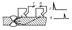
Crap. 10.
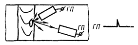
Crap. eleven.

Crap. 12.
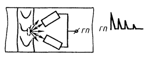
Crap. 13.
With the shadow method, a separate () circuit for switching on converters is used.
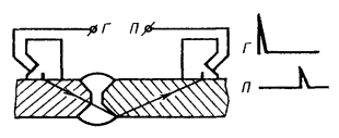
With the echo-shadow method, a separate-combined () scheme for switching on converters is used.
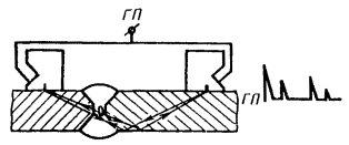
Crap. 15.
Note . On ; G- output to the generator of ultrasonic vibrations; P- output to the receiver.
3.2. Butt welded joints should be sounded according to the diagrams shown on, tee joints - according to the diagrams shown on, and lap joints - according to the diagrams shown on and.
It is allowed to use other schemes given in the technical documentation for control, approved in the prescribed manner.
3.3. Acoustic contact of the piezoelectric transducer with the controlled metal should be created by contact or immersion (slot) methods of introducing ultrasonic vibrations.
3.4. When searching for defects, the sensitivity (conditional or limiting) must exceed the specified value by the value established in the technical documentation for control, approved in the prescribed manner.
3.5. The sounding of the welded joint is performed according to the method of longitudinal and (or) transverse movement of the transducer at a constant or varying beam entry angle. The scanning method must be set in the technical documentation for control, approved in the prescribed manner.
3.6. Scanning steps (longitudinal Dcl or transverse Dct) is determined taking into account the specified excess of the search sensitivity over the evaluation sensitivity, the directivity pattern of the transducer and the thickness of the controlled welded joint. The methodology for determining the maximum scanning steps and is given in the recommended. For the nominal value of the scanning step during manual control, which must be observed during the control process, the following values should be taken:
Dcl= - 1 mm; Dct= - 1 mm.
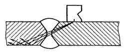
Crap. 16 .

Crap. 17 .

Crap. 18 .
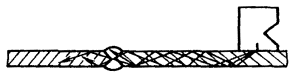
Crap. 19 .

Crap. 20 .
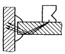
Crap. 21 .
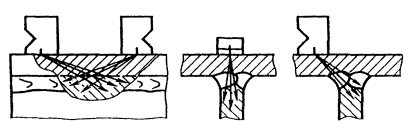
Crap. 22.

Crap. 23.

Crap. 24.
3.7. The method, basic parameters, transducer switching circuits, the method of introducing ultrasonic vibrations, the sounding circuit, as well as recommendations for separating false signals and signals from defects, must be indicated in the technical documentation for testing, approved in the prescribed manner.
4. EVALUATION AND PRESENTATION OF CONTROL RESULTS
4.1. Evaluation of control results
4.1.1. The assessment of the quality of welded joints according to ultrasonic testing data should be carried out in accordance with the normative and technical documentation for the product, approved in the prescribed manner.
4.1.2. The main measured characteristics of the identified defect are:
1) equivalent defect area S e or amplitude U d echo signal from a defect, taking into account the measured distance to it;
2) coordinates of the defect in the welded joint;
3) conditional dimensions of the defect;
4) conditional distance between defects;
5) the number of defects on a certain length of the connection.
The measured characteristics used to assess the quality of specific compounds must be indicated in the technical documentation for control, approved in the prescribed manner.
4.1.3. The equivalent area of the defect should be determined from the amplitude of the echo signal by comparing it with the amplitude of the echo signal from the reflector in the sample or by using calculated diagrams, provided that they agree with the experimental data by at least 20%.
4.1.4. The conditional dimensions of the identified defect are ():
1) conditional length DL;
2) conditional width DX;
3) conditional height DH.
Conditional length DL in millimeters, they are measured along the length of the zone between the extreme positions of the transducer, which is moved along the seam, oriented perpendicular to the axis of the seam.
Conditional Width DX in millimeters, they are measured along the length of the zone between the extreme positions of the transducer moving in the plane of incidence of the beam.
Nominal height DH in millimeters or microseconds is measured as the difference between the values of the depth of the defect in the extreme positions of the transducer moving in the plane of incidence of the beam.
4.1.5. When measuring conditional dimensions DL, DX, DH the extreme positions of the transducer are those at which the amplitude of the echo signal from the detected defect is either 0.5 of the maximum value, or decreases to a level corresponding to the specified sensitivity value.

Crap. 25.
It is allowed to take as extreme positions those at which the amplitude of the echo signal from the detected defect is a specified part from 0.8 to 0.2 of the maximum value. The accepted values of the levels should be specified when drawing up the results of the control.
Conditional Width DX and conditional height DH The defect is measured in the connection section, where the echo signal from the defect has the highest amplitude, at the same extreme positions of the transducer.
4.1.6. Conditional distance Dl(see) between defects measure the distance between the extreme positions of the transducer, at which the conditional length of two adjacent defects was determined.
4.1.7. An additional characteristic of the detected defect is its configuration and orientation.
To assess the orientation and configuration of the detected defect, use:
1) comparison of nominal sizes DL And DX detected defect with calculated or measured values of conditional dimensions DL 0 and DX 0 of a non-directional reflector located at the same depth as the identified defect.
When measuring conditional dimensions DL, DL 0 and DX, DX 0 for the extreme positions of the transducer are those at which the amplitude of the echo signal is a specified part from 0.8 to 0.2 of the maximum value specified in the technical documentation for control, approved in the prescribed manner;
2) echo amplitude comparison U 1 , reflected from the detected defect back to the transducer closest to the seam, with the amplitude of the echo signal U 2, which has undergone a mirror reflection from the inner surface of the connection and is received by two converters (see);
3) comparison of the ratio of the conditional dimensions of the identified defect DX/DH with the ratio of nominal dimensions of the cylindrical reflector DX 0 /DH 0 .
4) comparison of the second central moments of the conditional dimensions of the detected defect and a cylindrical reflector located at the same depth as the detected defect;
5) amplitude-time parameters of wave signals diffracted on the defect;
6) the spectrum of signals reflected from the defect;
7) determination of the coordinates of the reflecting points of the surface of the defect;
8) comparison of the amplitudes of the received signals from the defect and from the non-directional reflector when sounding the defect at different angles.
The necessity, possibility and methodology for assessing the configuration and orientation of the identified defect for connections of each type and size should be specified in the technical documentation for testing, approved in the prescribed manner.
4.2. Registration of control results
4.2.1. The results of the control should be recorded in a journal or conclusion, or on a welded joint diagram, or in another document, where the following should be indicated:
type of controlled joint, indices assigned to a given product and welded joint, and length of the controlled section;
technical documentation in accordance with which the control was carried out;
flaw detector type;
uncontrolled or incompletely controlled sections of welded joints subject to ultrasonic testing;
control results;
date of control;
surname of the flaw detector.
Additional information to be recorded, as well as the procedure for issuing and storing the journal (conclusions) must be specified in the technical documentation for control, approved in the prescribed manner.
4.2.2. The classification of butt welded joints according to the results of ultrasonic testing is carried out according to the mandatory.
The need for classification is stipulated in the technical documentation for control, approved in the prescribed manner.
4.2.3. In an abbreviated description of the inspection results, each defect or group of defects should be indicated separately and designated as:
a letter that qualitatively determines the assessment of the acceptability of a defect in terms of the equivalent area (amplitude of the echo signal) and conditional length (A, or D, or B, or DB);
a letter that qualitatively determines the conditional length of the defect, if it is measured in accordance with clause 4.7, listing 1 (D or F);
the letter defining the configuration of the defect, if it is set;
a figure that determines the equivalent area of the detected defect, mm 2, if it was measured;
a figure that determines the greatest depth of the defect, mm;
a figure that determines the conditional length of the defect, mm;
a figure that determines the conditional width of the defect, mm;
a figure that determines the conditional height of the defect, mm or µs.
4.2.4. The following notation should be used for abbreviation:
A - a defect, the equivalent area (amplitude of the echo signal) and the nominal length of which are equal to or less than the allowable values;
D - defect, the equivalent area (amplitude of the echo signal) which exceeds the allowable value;
B - defect, the conditional length of which exceeds the allowable value;
Г - defects, the conditional length of which DL £ DL 0 ;
E - defects, the conditional length of which DL > DL 0 ;
B - a group of defects separated from each other at distances Dl £ DL 0 ;
T - defects that are detected when the transducer is located at an angle to the weld axis and are not detected when the transducer is located perpendicular to the weld axis.
The nominal length for defects of types G and T is not indicated.
In the abbreviated notation, numerical values are separated from each other and from letter designations by a hyphen.
The need for an abbreviated notation, the designations used and the procedure for their notation are specified in the technical documentation for the control, approved in the prescribed manner.
5. SAFETY REQUIREMENTS
5.1. When carrying out work on ultrasonic testing of products, the flaw detector operator must be guided by GOST 12.1.001-83, GOST 12.2.003-74, GOST 12.3.002-75, the rules for the technical operation of consumer electrical installations and the technical safety rules for the operation of consumer electrical installations approved by the State Energy Supervision Authority.
5.2. When performing control, the requirements of the “Sanitary norms and rules for working with equipment that creates ultrasound transmitted by contact to the hands of workers” No. 2282-80, approved by the USSR Ministry of Health, and the safety requirements set forth in the technical documentation for the equipment used, approved in the established okay.
5.3. The noise levels generated at the workplace of the flaw detectorist should not exceed the permissible ones in accordance with GOST 12.1.003-83.
5.4. When organizing control work, fire safety requirements in accordance with GOST 12.1.004-85 must be observed.
ANNEX 1
Reference
EXPLANATION OF TERMS USED IN THE STANDARD
|
Term |
Definition |
|
Defect |
One discontinuity or a group of concentrated discontinuities, not provided for by design and technological documentation and independent of other discontinuities in terms of impact on the object |
|
Limiting sensitivity of echo-method control |
Sensitivity, characterized by the minimum equivalent area (in mm2) of a reflector that is still detectable at a given depth in the product at a given instrument setting |
|
Conditional sensitivity of echo-method control |
Sensitivity, characterized by the size and depth of detected artificial reflectors, made in a sample from a material with certain acoustic properties. In ultrasonic testing of welded joints, the conditional sensitivity is determined by the standard sample CO-1 or by the standard sample CO-2, or by the standard sample CO-2P. The conditional sensitivity according to the standard sample CO-1 is expressed by the greatest depth (in millimeters) of the location of the cylindrical reflector fixed by the indicators of the flaw detector. The conditional sensitivity according to the standard sample СО-2 (or СО-2Р) is expressed by the difference in decibels between the attenuator reading at a given flaw detector setting and the reading corresponding to the maximum attenuation at which a cylindrical hole with a diameter of 6 mm at a depth of 44 mm is fixed by the flaw detector indicators |
|
Acoustic axis |
According to GOST 23829-85 |
|
exit point |
According to GOST 23829-85 |
|
Converter boom |
According to GOST 23829-85 |
|
Entry angle |
The angle between the normal to the surface on which the transducer is installed and the line connecting the center of the cylindrical reflector with the exit point when the transducer is installed in a position at which the amplitude of the echo signal from the reflector is greatest |
|
Dead zone |
According to GOST 23829-85 |
|
Range resolution (beam) |
According to GOST 23829-85 |
|
Resolution front |
According to GOST 23829-85 |
|
Enterprise Standard Sample |
According to GOST 8.315-78 |
|
Industry standard sample |
According to GOST 8.315-78 |
|
Input surface |
According to GOST 23829-85 |
|
contact method |
According to GOST 23829-85 |
|
Immersion method |
According to GOST 23829-85 |
|
Depth gauge error |
Measurement error of the known distance to the reflector
Where s 2 - central moment; T- scanning trajectory on which the moment is determined;x- coordinate along the trajectory T; U(x) - signal amplitude at the pointx$
x 0 - average value of the coordinate for dependenceU(x):
For symmetrical dependenciesU(x) dot x 0 coincides with the point corresponding to the maximum amplitudeU(x) |
|
Second central normalized moments2н of the conditional size of the defect located at the depth H |
APPENDIX 2
Mandatory
METHODOLOGY FOR CONSTRUCTING A CERTIFICATE-GRAPH TO A STANDARD SAMPLE FROM ORGANIC DEFLECTION
The certificate-schedule establishes the connection of the conditional sensitivity () in millimeters according to the original standard sample CO-1 with the conditional sensitivity () in decibels according to the standard sample CO-2 (or CO-2R according to GOST 18576-85) and the number of the reflector with a diameter of 2 mm in the certified sample CO-1 at the frequency of ultrasonic vibrations (2.5 ± 0.2) MHz, temperature (20 ± 5) °C and prism anglesb= (40 ± 1)° or b= (50 ± 1)° for converters of a particular type.
In the drawing, dots indicate the graph for the original sample CO-1.

To build an appropriate graph for a specific certified sample CO-1 that does not meet the requirements of this standard, under the above conditions, the difference in amplitudes from reflectors No. 20 and 50 with a diameter of 2 mm in decibels is determined in the certified sample and the amplitudeN 0 from a reflector with a diameter of 6 mm at a depth of 44 mm in the CO-2 (or CO-2R) sample:
Where N 0 - attenuator reading corresponding to the attenuation of the echo signal from a hole with a diameter of 6 mm in the CO-2 (or CO-2P) sample to the level at which the conditional sensitivity is estimated, dB;
Attenuator reading at which the amplitude of the echo signal from the studied hole with the numberiin the certified sample reaches the level at which conditional sensitivity is estimated, dB.
The calculated values are marked with dots on the graph field and connected by a straight line (see the drawing for an example of construction).
EXAMPLES OF APPLICATION CERTIFICATE-SCHEDULE
The control is carried out by a flaw detector with a converter to a frequency of 2.5 MHz with a prism angleb= 40° and the radius of the piezoelectric plate A= 6 mm, manufactured in accordance with the specifications approved in the prescribed manner.
The flaw detector is equipped with a CO-1 sample, serial number, with a certificate schedule (see drawing).
1. The conditional sensitivity of 40 mm is specified in the technical documentation for testing.
The specified sensitivity will be reproduced if the flaw detector is adjusted to hole No. 45 in sample CO-1, serial number ________.
2. The conditional sensitivity of 13 dB is set by the technical documentation for the control. The specified sensitivity will be reproduced if the flaw detector is adjusted to hole No. 35 in sample CO-1, serial number ________.
APPENDIX 3
Reference
DETERMINATION OF THE PROPAGATION TIME OF ULTRASONIC OSCILLATIONS IN A TRANSDUCER PRISM
Time 2 t nin microseconds of propagation of ultrasonic vibrations in the transducer prism is
![]()
Where t 1 is the total time between the probing pulse and the echo signal from the concave cylindrical surface in the standard CO-3 sample when the transducer is set to the position corresponding to the maximum amplitude of the echo signal; 33.7 µs is the propagation time of ultrasonic vibrations in a standard sample, calculated for the following parameters: sample radius - 55 mm, transverse wave propagation velocity in the sample material - 3.26 mm/µs.
APPENDIX 4
CO-4 sample for measuring the wavelength and frequency of ultrasonic vibrations of transducers

1 - grooves; 2 - ruler; 3 - converter; 4 - block of steel grade 20 according to GOST 1050-74 or steel grade 3 according to GOST 14637-79; the difference in the depth of the grooves at the ends of the sample (h); sample width (l).
Standard sample CO-4 is used to measure the wavelength (frequency) excited by transducers with angles a input from 40 to 65 ° and a frequency of 1.25 to 5.00 MHz.
Wavelength l(frequency f) is determined by the interference method from the average value of the distances DL between four extrema of the amplitude of the echo signal from parallel grooves with a smoothly varying depth
![]()
Where g- the angle between the reflective surfaces of the grooves, equal to (see drawing)
![]()
Frequency fdetermined by the formula
f = c t/ l,
Where c t- velocity of transverse wave propagation in the sample material, m/s.
APPENDIX 5
Reference
Addiction N = f (e) for steel, aluminum and its alloys, titanium and its alloys

APPENDIX 6
METHOD FOR DETERMINING THE LIMITING SENSITIVITY OF A FLAW SCOPE AND THE EQUIVALENT AREA OF A DETECTED DEFECT ACCORDING TO A SAMPLE WITH A CYLINDRICAL HOLE
Limit sensitivity (S n) in square millimeters of angle-beam flaw detector (or equivalent areaSuhdetected defect) is determined according to the standard sample of the enterprise with a cylindrical hole or according to the standard sample CO-2A or CO-2 in accordance with the expression

Where N 0 - attenuator reading corresponding to the attenuation of the echo signal from the side cylindrical hole in the standard sample of the enterprise or in the standard sample of CO-2A, or CO-2 to the level at which the limiting sensitivity is estimated, dB;
N x- indication of the attenuator, at which the limiting sensitivity of the flaw detector is estimatedS nor at which the amplitude of the echo signal from the defect under study reaches the level at which the limiting sensitivity is estimated, dB;
DN- the difference between the transparency coefficients of the transducer prism boundary - the metal of the controlled connection and the transparency coefficient of the transducer prism boundary - the metal of the standard sample of the enterprise or the standard sample СО-2А (or СО-2), dB (DN£ 0).
When standardizing the sensitivity against a standard sample of the enterprise, which has the same shape and surface finish as the controlled compound,DN = 0;
b 0 - radius of a cylindrical hole, mm;
Shear wave velocity in the material of the sample and the controlled joint, m/s;
f- frequency of ultrasound, MHz;
r 1 - average path of ultrasound in the transducer prism, mm;
Longitudinal wave velocity in the prism material, m/s;
a And b- the angle of entry of the ultrasonic beam into the metal and the angle of the transducer prism, respectively, deg;
H- depth for which the limiting sensitivity is estimated or at which the detected defect is located, mm;
H 0 - depth of the cylindrical hole in the sample, mm;
dt- attenuation coefficient of the transverse wave in the metal of the controlled joint and sample, mm -1 .
To simplify the determination of the limiting sensitivity and the equivalent area, it is recommended to calculate and build a diagram (SKH-diagram) relating the limiting sensitivityS n(equivalent areaSuh), conditional coefficient TO defect detectability ![]() and depth H, for which the limit sensitivity is estimated (adjusted) or on which the detected defect is located.
and depth H, for which the limit sensitivity is estimated (adjusted) or on which the detected defect is located.
Convergence of calculated and experimental valuesS n at a= (50 ± 5)° no worse than 20%.
Construction example SKH -diagrams and definitions of limit sensitivity S n and equivalent area S uh
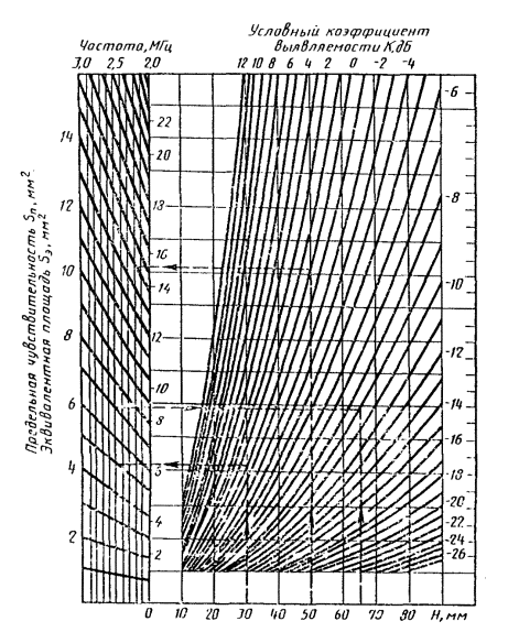
EXAMPLES
Inspection of butt welded joints of 50 mm thick sheets of mild steel is performed using an inclined transducer with known parameters:b, r 1 , . The frequency of ultrasonic vibrations excited by the transducer lies within 26.5 MHz ± 10%. Attenuation factordt= 0.001 mm -1.
When measured using a standard CO-2 sample, it was found thata= 50°. SKH diagram calculated for the stated conditions andb= 3 mm, H 0 = 44 mm according to the formula above, shown in the drawing.
Example 1
The measurement found thatf= 2.5 MHz. Standardization is carried out according to the standard sample of the enterprise with a cylindrical hole with a diameter of 6 mm, located at a depthH 0 = 44 mm; the shape and cleanliness of the surface of the sample corresponds to the shape and cleanliness of the surface of the tested compound.
The attenuator reading corresponding to the maximum attenuation at which an echo signal from a cylindrical hole in the sample is still recorded by the sound indicator isN 0 = 38 dB.
It is required to determine the limiting sensitivity for a given flaw detector setting (N x = N 0 =38 dB) and searching for defects at depthH= 30 mm.
The desired value of the limiting sensitivity on the SKH-diagram corresponds to the point of intersection of the ordinateH= 30mm with line K = N x - N 0 = 0 and is S n» 5 mm2.
It is required to adjust the flaw detector to the maximum sensitivityS n= 7 mm 2 for the depth of location of the desired defectsH= 65 mm, N 0 = 38 dB.
SetpointsS n And Haccording to the SKH diagram corresponds toK = N x - N 0 = -9 dB.
Then N x = K + N 0 = - 9 + 38 = 29 dB.
Example 2
The measurement found thatf= 2.2 MHz. The adjustment is carried out according to the standard sample CO-2 (H 0 = 44 mm). By comparing the amplitudes of echo signals from identical cylindrical holes in the sheets of the tested joint and in the standard sample CO-2, it was found thatDN= - 6 dB.
The attenuator reading corresponding to the maximum attenuation, at which the echo signal from the cylindrical hole in CO-2 is still recorded by an audible indicator, isN 0 = 43 dB.
It is required to determine the equivalent area of the detected defect. According to the measurements, the depth of the defectH= 50 mm, and the attenuator reading, at which the echo signal from the defect is still recorded,N x= 37 dB.
The desired value of the equivalent areaSuh, detected defect on SKH -diagram corresponds to the point of intersection of the ordinateH= 50 mm with line TO = N x - (N 0 + DN) = 37 - (43 - 6) = 0 dB and isSuh» 14 mm2.
APPENDIX 7
METHOD FOR DETERMINING THE MAXIMUM SCANNING STEP
Scanning step during transverse-longitudinal movement of the transducer with parametersn£ 15 mm and af= 15 mm MHz is determined by the nomogram shown in the drawing (m- way of sounding).

1 - a 0 = 65°, d= 20 mm and a 0 = 50°, d= 30 mm; 2- a 0 = 50°, d= 40 mm; 3- a 0 = 65°, d= 30 mm; 4 - a 0 = 50°, d= 50 mm; 5 - a 0 = 50°, d= 60 mm.
Examples :
1. Set Snn/ S n 0 = 6 dB, m = 0, a= 50°. According to the nomogram = 3 mm.
2. Set a= 50°, d= 40 mm, m= 1, = 4 mm. According to the nomogramSnn/ S n 0 » 2 dB.
The scanning step during longitudinal-transverse movement of the transducer is determined by the formula
Where i- 1, 2, 3, etc. - step sequence number;
L i- distance from the exit point to the scanned section, normal to the contact surface of the controlled object.
Parameter Yis determined experimentally by a cylindrical hole in the CO-2 or CO-2A sample, or by the standard sample of the enterprise. To do this, measure the nominal width of the cylindrical holeDXwith a weakening of the maximum amplitude equal toSnn/ S n 0 and minimum distanceLminfrom the projection of the center of the reflector on the working surface of the sample to the input point of the transducer, which is in the position at which the conditional width was determinedDX. Meaning Y icalculated according to the formula
![]()
Where ![]() - the reduced distance from the emitter to the beam exit point in the transducer.
- the reduced distance from the emitter to the beam exit point in the transducer.
APPENDIX 8
Mandatory
CLASSIFICATION OF DEFECTIVENESS OF BUTT WELDS ACCORDING TO THE RESULTS OF ULTRASONIC TESTING
1. This annex applies to butt welds of main pipelines and building structures and establishes the classification of defectiveness of butt welds of metals and their alloys with a thickness of 4 mm or more based on the results of ultrasonic testing.
The application is a unified section of the USSR standard and the GDR standard according to the following main features:
designation and name of defects in welds;
assignment of defects to one of the types;
determination of defect size steps;
establishment of defect frequency steps;
determination of the length of the appraisal section;
establishment of the class of defectiveness depending on the type of defects, size step and frequency step of defects.
2. The main measured characteristics of the identified defects are:
diameter Dequivalent disk reflector;
defect coordinates (H, x) in section ();
conditional dimensions of the defect (see);
echo amplitude ratioU 1 , reflected from the detected defect, and the echo signalU 2 , which has undergone mirror reflection from the inner surface ();
corner gturning the transducer between the extreme positions, at which the maximum amplitude of the echo signal from the edge of the detected defect is halved in relation to the maximum amplitude of the echo signal when the transducer is located perpendicular to the weld axis ().

Crap. 1 .

Crap. 2.
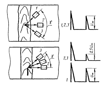
Crap. 3.
The characteristics used to assess the quality of specific welds, the procedure and accuracy of their measurements should be established in the technical documentation for control.
3. Diameter DThe equivalent disk reflector is determined using a diagram or standard (test) samples by the maximum amplitude of the echo signal from the detected defect.
4. The conditional dimensions of the identified defect are (see):
conditional lengthDL;
conditional width DX;
conditional height DH.
5. Conditional lengthDLin millimeters, they are measured along the length of the zone between the extreme positions of the transducer, which is moved along the seam, oriented perpendicular to the axis of the seam.
Conditional Width DXin millimeters, they are measured along the length of the zone between the extreme positions of the transducer, which is moved perpendicular to the seam.
Nominal height DHin millimeters (or microseconds) is measured as the difference in depth values (H 2 , H 1) the location of the defect in the extreme positions of the transducer, which is moved perpendicular to the seam.
The extreme positions of the transducer are those at which the amplitude of the echo signal from the detected defect decreases to a level that is a specified part of the maximum value and established in the technical documentation for control, approved in the prescribed manner.
GOST R 55724-2013
NATIONAL STANDARD OF THE RUSSIAN FEDERATION
NON-DESTRUCTIVE CONTROL. WELDED CONNECTIONS
Ultrasonic methods
non-destructive testing. Welded joints. Ultrasonic methods
Introduction date 2015-07-01
Foreword
Foreword
1 DEVELOPED by the Federal State Enterprise "Research Institute of Bridges and Flaw Detection of the Federal Agency for Railway Transport" (NII Bridges), the State Scientific Center of the Russian Federation "Open Joint-Stock Company" Scientific and Production Association "Central Research Institute of Engineering Technology" (OJSC NPO "CNIITMASH "), Federal State Autonomous Institution "Scientific and Educational Center "Welding and Control" at the Moscow State Technical University named after N.E. Bauman"
2 INTRODUCED by the Technical Committee for Standardization TC 371 "Non-Destructive Testing"
3 APPROVED AND PUT INTO EFFECT by Order of the Federal Agency for Technical Regulation and Metrology of November 8, 2013 N 1410-st
4 INTRODUCED FOR THE FIRST TIME
5 REVISION. April 2019
The rules for the application of this standard are set out in Article 26 of the Federal Law of June 29, 2015 N 162-FZ "On standardization in the Russian Federation" . Information about changes to this standard is published in the annual (as of January 1 of the current year) information index "National Standards", and the official text of changes and amendments - in the monthly information index "National Standards". In case of revision (replacement) or cancellation of this standard, a corresponding notice will be published in the next issue of the monthly information index "National Standards". Relevant information, notification and texts are also posted in the public information system - on the official website of the Federal Agency for Technical Regulation and Metrology on the Internet (www.gost.ru)
1 area of use
This standard establishes methods for ultrasonic testing of butt, fillet, lap and tee joints with full root penetration, made by arc, electroslag, gas, gas pressure, electron beam, laser and flash butt welding or their combinations, in welded products made of metals and alloys for detection of the following discontinuities: cracks, lack of penetration, pores, non-metallic and metallic inclusions.
This standard does not regulate methods for determining the actual size, type and shape of the identified discontinuities (defects) and does not apply to the control of anti-corrosion surfacing.
The need for and scope of ultrasonic testing, types and sizes of discontinuities (defects) to be detected are established in the standards or design documentation for products.
2 Normative references
This standard uses normative references to the following standards:
GOST 12.1.001 Occupational safety standards system. Ultrasound. General safety requirements
GOST 12.1.003 Occupational safety standards system. Noise. General safety requirements
GOST 12.1.004 Occupational safety standards system. Fire safety. General requirements
GOST 12.2.003 Occupational safety standards system. Production equipment. General safety requirements
GOST 12.3.002 Occupational safety standards system. Manufacturing processes. General safety requirements
GOST 2789 Surface roughness. Parameters and characteristics
GOST 18353 * Non-destructive testing. Classification of types and methods
________________
* Lost power. GOST R 56542-2015 is valid.
GOST 18576-96 Non-destructive testing. Railway rails. Ultrasonic methods
GOST R 55725 Non-destructive testing. Ultrasonic piezoelectric transducers. General technical requirements
GOST R 55808 Non-destructive testing. Ultrasonic transducers. Test Methods
Note - When using this standard, it is advisable to check the validity of reference standards in the public information system - on the official website of the Federal Agency for Technical Regulation and Metrology on the Internet or according to the annual information index "National Standards", which was published as of January 1 of the current year, and on issues of the monthly information index "National Standards" for the current year. If an undated referenced reference standard has been replaced, it is recommended that the current version of that standard be used, taking into account any changes made to that version. If the reference standard to which the dated reference is given is replaced, then it is recommended to use the version of this standard with the year of approval (acceptance) indicated above. If, after the approval of this standard, a change is made to the referenced standard to which a dated reference is given, affecting the provision to which the reference is given, then this provision is recommended to be applied without taking into account this change. If the reference standard is canceled without replacement, then the provision in which the reference to it is given is recommended to be applied in the part that does not affect this reference.
3 Terms and definitions
3.1 The following terms are used in this standard with their respective definitions:
3.1.19 SKH diagram: Graphic representation of the dependence of the detection coefficient on the depth of the flat-bottomed artificial reflector, taking into account its size and type of transducer.
3.1.20 rejection sensitivity level: The level of sensitivity at which a decision is made to classify the identified discontinuity as a "defect".
3.1.21 diffraction method: A method of ultrasonic testing by the method of reflections, using separate emitting and receiving transducers and based on the reception and analysis of the amplitude and/or temporal characteristics of wave signals diffracted by a discontinuity.
3.1.22 control sensitivity level (fixation level): The level of sensitivity at which discontinuities are registered and their acceptability is assessed in terms of nominal size and quantity.
3.1.23 reference signal: The signal from an artificial or natural reflector in a sample of a material with specified properties or a signal that has passed through the controlled product, which is used to determine and adjust the reference level of sensitivity and/or measured discontinuity characteristics.
3.1.24 reference sensitivity level: Sensitivity level at which the reference signal has a given height on the flaw detector screen.
3.1.25 depth gauge error: The measurement error of the known distance to the reflector.
3.1.26 search sensitivity level: Sensitivity level set when searching for discontinuities.
3.1.27 limiting sensitivity of echo-method control: Sensitivity, characterized by the minimum equivalent area (in mm) of a reflector that is still detectable at a given depth in the product at a given instrument setting.
3.1.28 input angle: The angle between the normal to the surface on which the transducer is mounted and the line connecting the center of the cylindrical reflector to the beam exit point when the transducer is set to the position at which the amplitude of the echo signal from the reflector is greatest.
3.1.29 conditional size (length, width, height) of the defect: The size in millimeters corresponding to the zone between the extreme positions of the transducer, within which the signal from discontinuity is recorded at a given sensitivity level.
3.1.30 conditional distance between discontinuities: The minimum distance between the positions of the transducer, at which the amplitudes of the echo signals from discontinuities are fixed at a given sensitivity level.
3.1.31 conditional sensitivity of echo-method control: Sensitivity, which is determined by the measure of CO-2 (or CO-3P) and is expressed by the difference in decibels between the attenuator (calibrated amplifier) reading at a given flaw detector setting and the reading corresponding to the maximum attenuation (gain) at which a cylindrical hole with a diameter of 6 mm at a depth 44 mm is fixed by flaw detector indicators.
3.1.32 scan step: The distance between adjacent trajectories of the transducer beam exit point on the surface of the controlled object.
3.1.33 equivalent discontinuity area: The area of a flat-bottomed artificial reflector oriented perpendicular to the acoustic axis of the transducer and located at the same distance from the input surface as the discontinuity, at which the values of the signal of the acoustic device from the discontinuity and the reflector are equal.
3.1.34 equivalent sensitivity: Sensitivity expressed as the difference in decibels between the gain value at a given flaw detector setting and the gain value at which the amplitude of the echo signal from the reference reflector reaches the specified value along the y-axis of the type A sweep.
4 Symbols and abbreviations
4.1 The following symbols are used in this standard:
I - emitter;
P - receiver;
Conditional defect height;
Conditional length of the defect;
Conditional distance between defects;
Conditional defect width;
Sensitivity limit;
Transverse scan step;
Longitudinal scan step.
4.2 The following abbreviations are used in this standard:
BCO - side cylindrical hole;
BUT - tuning sample;
PEP - piezoelectric transducer;
US - ultrasound (ultrasonic);
UZK - ultrasonic control;
EMAP - electromagnetic acoustic transducer.
5 General provisions
5.1 When ultrasonic testing of welded joints, methods of reflected radiation and transmitted radiation are used in accordance with GOST 18353, as well as their combinations, implemented by methods (method options), sounding schemes regulated by this standard.
5.2 In ultrasonic testing of welded joints, the following types of ultrasonic waves are used: longitudinal, transverse, surface, longitudinal subsurface (head).
5.3 For ultrasonic testing of welded joints, the following means of control are used:
- ultrasonic pulse flaw detector or hardware-software complex (hereinafter referred to as flaw detector);
- transducers (PEP, EMAT) in accordance with GOST R 55725 or non-standardized transducers (including multi-element), certified (calibrated) in accordance with the requirements of GOST R 55725;
- measures and/or NOs for adjusting and checking the parameters of the flaw detector.
Additionally, auxiliary devices and devices can be used to comply with scanning parameters, measure the characteristics of detected defects, assess roughness, etc.
5.4 Flaw detectors with transducers, measures, NO, auxiliary devices and devices used for ultrasonic testing of welded joints should ensure the possibility of implementing methods and methods of ultrasonic testing from among those contained in this standard.
5.5 Measuring instruments (flaw detectors with transducers, measures, etc.) used for ultrasonic testing of welded joints are subject to metrological support (control) in accordance with the current legislation.
5.6 Technological documentation for ultrasonic testing of welded joints should regulate: types of tested welded joints and requirements for their testability; qualification requirements for personnel performing ultrasonic testing and quality assessment; the need for ultrasonic testing of the near-weld zone, its dimensions, control methods and quality requirements; control zones, types and characteristics of defects to be detected; methods of control, types of means and auxiliary equipment used for control; values of the main control parameters and methods for their adjustment; sequence of operations; ways to interpret and record results; criteria for assessing the quality of objects based on the results of ultrasonic testing.
6 Control methods, sounding schemes and methods for scanning welded joints
6.1 Control methods
In ultrasonic testing of welded joints, the following methods (variants of methods) of control are used: echo-pulse, mirror-shadow, echo-shadow, echo-mirror, diffraction, delta (Figures 1-6).
It is allowed to use other methods of ultrasonic testing of welded joints, the reliability of which is confirmed theoretically and experimentally.
Ultrasonic testing methods are implemented using transducers connected according to combined or separate circuits.
Figure 1 - Pulse Echo
Figure 2 - Mirror-Shadow
Figure 3 - Echo-shadow direct (a) and inclined (b) probe
Figure 4 - Echo Mirror
Figure 5 - Diffractive
Figure 6 - Variants of the delta method
6.2 Sounding schemes for various types of welded joints
6.2.1 Ultrasonic testing of butt welded joints is carried out by direct and inclined transducers using sounding schemes with direct, single-reflected, double-reflected beams (Figures 7-9).
It is allowed to use other sounding schemes given in the technological documentation for testing.
Figure 7 - Scheme of sounding a butt welded joint with a direct beam
Figure 8 - Scheme of sounding of a butt welded joint with a single-reflected beam
Figure 9 - Scheme of sounding of a butt welded joint with a double-reflected beam
6.2.2 Ultrasonic testing of tee welded joints is carried out by direct and inclined transducers using sounding schemes with direct and (or) single-reflected beams (Figures 10-12).
Note - In the figures, the symbol indicates the direction of sounding by an inclined probe "from the observer". With these schemes, sounding is performed similarly in the direction "towards the observer".
Figure 10 - Schemes of sounding of a tee welded joint by direct (a) and single-reflected (b) beams
Figure 11 - Schemes of sounding a T-welded joint with a direct beam
Figure 12 - Scheme of sounding a tee welded joint with inclined transducers according to a separate scheme (H-lack of penetration)
6.2.3 Ultrasonic testing of fillet welded joints is carried out by direct and inclined transducers using sounding schemes with direct and (or) single-reflected beams (Figures 13-15).
It is allowed to use other schemes given in the technological documentation for control.
Figure 13 - Scheme of sounding of a fillet welded joint with combined oblique and direct transducers
Figure 14 - Scheme of sounding of a fillet welded joint with bilateral access by combined oblique and direct transducers, transducers of subsurface (head) waves
Figure 15 - Scheme of sounding of a fillet welded joint with one-sided access by combined oblique and direct transducers, transducers of subsurface (head) waves
6.2.4 Ultrasonic testing of lap welded joints is carried out by inclined transducers using sounding circuits shown in Figure 16.
Figure 16 - Scheme of sounding of a lap welded joint according to combined (a) or separate (b) schemes
6.2.5 Ultrasound testing of welded joints in order to detect transverse cracks (including those in joints with a removed weld bead) is performed by inclined transducers using sounding schemes shown in Figures 13, 14, 17.
Figure 17 - Scheme of sounding of butt welded joints during control to search for transverse cracks: a) - with the weld bead removed; b) - with an unremoved seam roller
6.2.6 Ultrasound examination of welded joints in order to detect discontinuities lying near the surface on which scanning is performed is performed by longitudinal subsurface (head) waves or surface waves (for example, Figures 14, 15).
6.2.7 Ultrasound testing of butt welded joints at the intersections of the seams is performed by inclined transducers using the sounding schemes shown in Figure 18.
Figure 18 - Schemes of sounding of the intersections of butt welded joints
6.3 Scanning methods
6.3.1 Scanning of a welded joint is carried out according to the method of longitudinal and (or) transverse movement of the transducer at constant or varying angles of input and turn of the beam. The method of scanning, the direction of sounding, the surfaces from which sounding is carried out, must be established taking into account the purpose and testability of the connection in the technological documentation for testing.
6.3.2 In ultrasonic testing of welded joints, transverse-longitudinal (Figure 19) or longitudinal-transverse (Figure 20) scanning methods are used. It is also allowed to use the sweeping beam scanning method (Figure 21).
Figure 19 - Variants of the method of transverse-longitudinal scanning
Figure 20 - The method of transverse-longitudinal scanning
Figure 21 - Sweeping beam scanning method
7 Requirements for controls
7.1 Flaw detectors used for ultrasonic testing of welded joints must provide adjustment of amplification (attenuation) of signal amplitudes, measurement of the ratio of signal amplitudes over the entire range of amplification (attenuation) adjustment, measurement of the distance traveled by an ultrasonic pulse in the test object to the reflecting surface, and the coordinates of the location of the reflecting surface relative to the exit point of the beam.
7.2 Transducers used in conjunction with flaw detectors for ultrasonic testing of welded joints must provide:
- deviation of the operating frequency of ultrasonic vibrations emitted by transducers from the nominal value - no more than 20% (for frequencies no more than 1.25 MHz), no more than 10% (for frequencies above 1.25 MHz);
- deviation of the beam entry angle from the nominal value - no more than ±2°;
- deviation of the beam exit point from the position of the corresponding mark on the transducer - no more than ±1 mm.
The shape and dimensions of the transducer, the values of the boom of the inclined transducer and the average ultrasonic path in the prism (tread) must comply with the requirements of the technological documentation for testing.
7.3 Measures and reference blocks
7.3.1 In ultrasonic testing of welded joints, measures and/or NDs are used, the scope and verification (calibration) conditions of which are specified in the technological documentation for ultrasonic testing.
7.3.2 Measures (calibration samples) used for ultrasonic testing of welded joints must have metrological characteristics that ensure repeatability and reproducibility of measurements of echo signal amplitudes and time intervals between echo signals, according to which the main parameters of ultrasonic testing, regulated by technological documentation, are adjusted and checked at the ultrasound.
Samples CO-2, CO-3, or CO-3R according to GOST 18576, the requirements for which are given in Appendix A, can be used as measures for adjusting and checking the main parameters of ultrasonic testing with flat-surface transducers for a frequency of 1.25 MHz or more.
7.3.3 NRs used for ultrasonic testing of welded joints must provide the possibility of setting the time intervals and sensitivity values specified in the technological documentation for ultrasonic testing, and have a certificate containing the values of geometric parameters and the ratio of amplitudes of echo signals from reflectors in RL and measures, and also the identification data of the measures used in the certification.
Samples with flat-bottomed reflectors, as well as samples with BCO, segment or corner reflectors are used as NO for setting and checking the main parameters of ultrasonic testing.
It is also allowed to use calibration samples V1 according to ISO 2400:2012, V2 according to ISO 7963:2006 (Appendix B) or their modifications, as well as samples made from test objects, with constructive reflectors or alternative reflectors of arbitrary shape as NR.
8 Preparing for testing
8.1 The welded joint is prepared for ultrasonic testing if there are no external defects in the joint. The shape and dimensions of the near-weld zone should allow the transducer to be moved within the limits determined by the degree of testability of the joint (Appendix B).
8.2 The connection surface along which the transducer is moved must not have dents and irregularities; metal spatter, peeling scale and paint, and contamination must be removed from the surface.
When machining the joint, provided for by the technological process for the manufacture of a welded structure, the surface roughness must be no worse than 40 microns in accordance with GOST 2789.
The requirements for surface preparation, permissible roughness and waviness, methods for measuring them (if necessary), as well as the presence of non-peeling scale, paint and contamination of the surface of the test object are indicated in the technological documentation for control.
8.3 Non-destructive testing of the near-weld zone of the base metal for the absence of delaminations that prevent ultrasonic testing by an inclined transducer is performed in accordance with the requirements of technological documentation.
8.4 The welded joint should be marked and divided into sections so as to unambiguously determine the location of the defect along the length of the weld.
8.5 Pipes and tanks must be emptied of liquid before inspection by reflected beam.
It is allowed to control pipes, tanks, ship hulls with liquid under the bottom surface according to the methods regulated by the technological documentation for control.
8.6 Basic control parameters:
a) the frequency of ultrasonic vibrations;
b) sensitivity;
c) the position of the beam exit point (arrow) of the transducer;
d) beam entry angle into the metal;
e) coordinate measurement error or depth gauge error;
e) dead zone;
g) resolution;
i) the opening angle of the radiation pattern in the plane of incidence of the wave;
j) scan step.
8.7 The frequency of ultrasonic vibrations should be measured as the effective frequency of the echo pulse according to GOST R 55808.
8.8 The main parameters according to b)-i) 8.6 should be adjusted (checked) according to measures or NO.
8.8.1 Conditional sensitivity for echo-pulse ultrasonic testing should be adjusted according to CO-2 or CO-3R measures in decibels.
The conditional sensitivity for mirror-shadow ultrasonic testing should be adjusted on a defect-free section of the welded joint or on the NO in accordance with GOST 18576.
8.8.2 Limiting sensitivity during echo-pulse ultrasonic testing should be adjusted according to the area of flat-bottomed reflector in BUT or according to DGS, SKH-diagrams.
It is allowed to use instead of NO with a flat-bottomed reflector NO with segment, corner reflectors, BCO or other reflectors. The method of setting the limit sensitivity for such samples should be regulated in the technological documentation for ultrasonic testing. At the same time, for NO with a segment reflector
where is the area of the segment reflector;
and for NO with a corner reflector
where is the area of the corner reflector;
- coefficient, the values of which for steel, aluminum and its alloys, titanium and its alloys are shown in Figure 22.
When using DGS, SKH-diagrams, echo signals from reflectors in measures CO-2, CO-3, as well as from the bottom surface or dihedral angle in the controlled product or in the NO are used as a reference signal.
Figure 22 - Graph for determining the correction to the limit sensitivity when using a corner reflector
8.8.3 Equivalent sensitivity for echo-pulse ultrasonic testing should be adjusted according to the NO, taking into account the requirements of 7.3.3.
8.8.4 When setting the sensitivity, a correction should be introduced that takes into account the difference in the state of the surfaces of the measure or HO and the controlled joint (roughness, coatings, curvature). Methods for determining the corrections must be indicated in the technological documentation for control.
8.8.5 The angle of beam entry should be measured by measures or HO at an ambient temperature corresponding to the control temperature.
The angle of beam entry when testing welded joints with a thickness of more than 100 mm is determined in accordance with the technological documentation for testing.
8.8.6 The error in measuring coordinates or the error of the depth gauge, the dead zone, the angle of opening of the radiation pattern in the plane of incidence of the wave should be measured using CO-2, CO-3R or HO measures.
9 Carrying out control
9.1 The sounding of the welded joint is performed according to the schemes and methods given in Section 6.
9.2 Acoustic contact between the probe and the metal to be tested should be created by contact, or immersion, or slot methods for introducing ultrasonic vibrations.
9.3 Scanning steps , are determined taking into account the specified excess of the search sensitivity level over the control sensitivity level, the transducer radiation pattern and the thickness of the controlled welded joint, while the scanning step should be no more than half the size of the PET active element in the step direction.
9.4 When performing ultrasonic testing, the following sensitivity levels are used: reference level; control level; rejection level; search level.
The quantitative difference between sensitivity levels should be regulated by the technological documentation for control.
9.5 Scanning speed during manual ultrasonic testing should not exceed 150 mm/s.
9.6 To detect defects located at the ends of the connection, additionally sound the zone at each end, gradually turning the transducer towards the end at an angle of up to 45°.
9.7 In the case of ultrasonic testing of welded joints of products with a diameter of less than 800 mm, the adjustment of the control zone should be carried out using artificial reflectors made in NR, having the same thickness and radius of curvature as the tested product. Permissible deviation along the radius of the sample - no more than 10% of the nominal value. When scanning on an outer or inner surface with a curvature radius of less than 400 mm, the prisms of inclined probes must correspond to the surface (be lapped). During the control of the RS probe and straight probes, special nozzles should be used to ensure the constant orientation of the probe perpendicular to the scanning surface.
Processing (grinding) of the probe must be carried out in a device that excludes the distortion of the probe relative to the normal to the input surface.
Features of setting the main parameters and carrying out control of cylindrical products are indicated in the technological documentation for ultrasonic testing.
9.8 The stage of scanning during mechanized or automated ultrasonic testing with the help of special scanning devices should be performed taking into account the recommendations of the Equipment Operation Manuals.
10 Defect characterization and quality assessment
10.1 The main measured characteristics of the identified discontinuity are:
- the ratio of the amplitude and/or time characteristics of the received signal and the corresponding characteristics of the reference signal;
- equivalent discontinuity area;
- coordinates of the discontinuity in the welded joint;
- conditional dimensions of the discontinuity;
- conditional distance between discontinuities;
- the number of discontinuities in a certain length of the connection.
The measured characteristics used to assess the quality of specific compounds should be regulated by the technological documentation for control.
10.2 The equivalent area is determined by the maximum amplitude of the echo signal from the discontinuity by comparing it with the amplitude of the echo signal from the reflector in the NO or by using calculated diagrams, provided that they converge with the experimental data by at least 20%.
10.3 The following can be used as conditional dimensions of the revealed discontinuity: conditional length ; conditional width ; conditional height (Figure 23).
The conditional length is measured by the length of the zone between the extreme positions of the transducer, which is moved along the seam and oriented perpendicular to the seam axis.
The conditional width is measured by the length of the zone between the extreme positions of the transducer, which is moved in the plane of incidence of the beam.
The nominal height is determined as the difference between the measured values of the discontinuity location depth in the extreme positions of the transducer moving in the beam incidence plane.
10.4 When measuring conditional dimensions , , the extreme positions of the transducer are those at which the amplitude of the echo signal from the detected discontinuity is either 0.5 of the maximum value (the relative measurement level is 0.5), or corresponds to the specified sensitivity level.
It is allowed to measure the conditional dimensions of discontinuities at values of the relative level of measurements from 0.8 to 0.1, if this is indicated in the technological documentation for ultrasonic testing.
The conditional width and conditional height of an extended discontinuity are measured in the joint section, where the echo signal from the discontinuity has the highest amplitude, as well as in the sections located at the distances specified in the technological documentation for testing.
Figure 23 - Measurement of the conditional dimensions of defects
10.5 The conditional distance between discontinuities is measured by the distance between the extreme positions of the transducer. In this case, the extreme positions are set depending on the length of discontinuities:
- for a compact discontinuity (, where is the conditional length of a non-directional reflector lying at the same depth as the discontinuity), the extreme position of the transducer is taken at which the amplitude of the echo signal is maximum;
- for an extended discontinuity (), the extreme position of the transducer is taken, at which the amplitude of the echo signal corresponds to the specified sensitivity level.
10.6 Welded joints in which the measured value of at least one characteristic of the detected defect is greater than the rejection value of this characteristic specified in the technological documentation do not meet the requirements of ultrasonic testing.
11 Registration of control results
11.1 The results of ultrasonic testing should be reflected in the working, accounting and acceptance documentation, the list and forms of which are accepted in the prescribed manner. Documentation must contain information:
- about the type of controlled joint, indices assigned to the product and welded joint, location and length of the section subject to ultrasonic testing;
- technological documentation, in accordance with which ultrasonic testing is performed and its results are evaluated;
- date of control;
- identification data of the flaw detector;
- type and serial number of the flaw detector, transducers, measures, NO;
- uncontrolled or incompletely controlled areas subject to ultrasonic testing;
- Ultrasound results.
11.2 Additional information to be recorded, the procedure for registration and storage of the journal (conclusions, as well as the form for presenting the results of control to the customer) should be regulated by the technological documentation for ultrasonic testing.
11.3 The need for an abbreviated record of the results of control, the designations used and the procedure for recording them should be regulated by the technological documentation for ultrasonic testing. For abbreviated notation, the designations according to Appendix D can be used.
12 Safety requirements
12.1 When carrying out work on ultrasonic testing of products, the flaw detectorist must be guided by GOST 12.1.001, GOST 12.2.003, GOST 12.3.002, the rules for the technical operation of consumer electrical installations and the technical safety rules for the operation of consumer electrical installations approved by Rostekhnadzor.
12.2 When performing control, the requirements and safety requirements set forth in the technical documentation for the equipment used, approved in the prescribed manner, must be observed.
12.3 The noise levels generated at the workplace of the flaw detectorist should not exceed the permissible ones in accordance with GOST 12.1.003.
12.4 When organizing control work, fire safety requirements in accordance with GOST 12.1.004 must be observed.
Annex A (mandatory). Measures СО-2, СО-3, СО-3Р for checking (setting) the main parameters of ultrasonic testing
Annex A
(mandatory)
A.1 Measures CO-2 (Figure A.1), CO-3 (Figure A.2), CO-3R according to GOST 18576 (Figure A.3) should be made of steel grade 20 and used for measuring (setting) and verification of the main parameters of equipment and control by converters with a flat working surface at a frequency of 1.25 MHz or more.
Figure A.1 — Sketch of measure CO-2
Figure A.2 — Sketch of CO-3 measure
Figure A.3 — Sketch of measure CO-3P
A.2 The CO-2 measure should be used to set the conditional sensitivity, as well as to check the dead zone, the error of the depth gauge, the beam entry angle, the opening angle of the main lobe of the directivity pattern in the plane of incidence, and to determine the maximum sensitivity when testing joints made of steel.
A.3 When testing compounds made of metals that differ in acoustic characteristics from carbon and low-alloy steels (in terms of longitudinal wave propagation velocity by more than 5%) to determine the beam entry angle, the opening angle of the main lobe of the directivity pattern, the dead zone, as well as the limiting sensitivity HO SO-2A, made of a controlled material, should be used.
A.4 Measure CO-3 should be used to determine the point of exit of the beam and boom of the transducer.
A.5 Measure CO-3P should be used to determine and adjust the basic parameters listed in 8.8 for measures CO-2 and CO-3.
Appendix B (informative). Tuning samples for checking (setting) the main parameters of ultrasonic testing
Annex B
(reference)
B.1 BUT with a flat-bottomed reflector is metal block, made of a controlled material, in which a flat-bottomed reflector is made, oriented perpendicular to the acoustic axis of the transducer. The depth of the flat-bottomed reflector must comply with the requirements of the technological documentation.
1 - the bottom of the hole; 2 - converter; 3 - a block of controlled metal; 4 - acoustic axis
Figure B.1 - Sketch of a NO with a flat-bottomed reflector
B.2 NO V1 according to ISO 2400:2012 is a metal block (figure B.1) made of carbon steel, into which a cylinder with a diameter of 50 mm, made of plexiglass, is pressed.
BUT V1 is used to adjust the sweep parameters of the flaw detector and depth gauge, adjust the sensitivity levels, as well as to evaluate the dead zone, resolution, determine the point of exit of the beam, arrow and the angle of entry of the transducer.
B.3 NO V2 according to ISO 7963:2006 is made of carbon steel (Figure B.2) and is used to set the depth gauge, set sensitivity levels, determine the point of exit of the beam, arrow and the angle of entry of the transducer.
Figure B.2 - Sketch NO V1
Figure B.3 - Sketch of NO V2
Annex B (recommended). Degrees of testability of welded joints
For seams of welded joints, the following degrees of testability are established in descending order:
1 - the acoustic axis crosses each element (point) of the controlled section from at least two directions, depending on the requirements of the technological documentation;
2 - the acoustic axis crosses each element (point) of the controlled section from one direction;
3 - there are elements of a controlled section, which, with a regulated sounding scheme, the acoustic axis of the radiation pattern does not cross in any of the directions. In this case, the area of non-sound areas does not exceed 20% of the total area of the controlled section, and they are located only in the subsurface part of the welded joint.
Directions are considered different if the angle between the acoustic axes is at least 15°.
Any degree of testability, except for 1, is established in the technological documentation for control.
In an abbreviated description of the inspection results, each defect or group of defects should be indicated separately and denoted by a letter:
- a letter that determines qualitatively the assessment of the acceptability of a defect in terms of the equivalent area (amplitude of the echo signal - A or D) and conditional length (B);
- a letter that qualitatively determines the conditional length of the defect, if it is measured in accordance with 10.3 (D or F);
- a letter that defines the configuration (volumetric - W, planar - P) of the defect, if it is installed;
- a figure that determines the equivalent area of the detected defect, mm, if it was measured;
- a number that determines the maximum depth of the defect, mm;
- a number that determines the conditional length of the defect, mm;
- a number that determines the conditional width of the defect, mm;
- a number that determines the conditional height of the defect, mm or µs*.
________________
* The text of the document corresponds to the original. - Database manufacturer's note.
The following notation should be used for abbreviation:
A - a defect, the equivalent area (amplitude of the echo signal) and the conditional length of which are equal to or less than the allowable values;
D - defect, the equivalent area (amplitude of the echo signal) which exceeds the allowable value;
B - defect, the conditional length of which exceeds the allowable value;
G - defect, the conditional length of which;
E - defect, the conditional length of which;
B - a group of defects separated from each other at distances ;
T - a defect that, when the transducer is located at an angle of less than 40 ° to the weld axis, causes the appearance of an echo signal exceeding the amplitude of the echo signal when the transducer is located perpendicular to the weld axis, by the value specified in the technical documentation for testing, approved in the prescribed manner.
The nominal length for defects of types G and T is not indicated.
In the abbreviated notation, numerical values are separated from each other and from letter designations by a hyphen.
Bibliography
UDC 621.791.053:620.169.16:006.354 | |
Keywords: non-destructive testing, welded seams, ultrasonic methods |
|
Electronic text of the document
prepared by Kodeks JSC and verified against:
official publication
Moscow: Standartinform, 2019