Selection of analog designs when developing a training sailing vessel for inland waterways. Brief description of analogue projects
The article presents an analysis of analogue projects considered during the development of a training sailing vessel for inland waterways.
1. Naval boat TS OSAVIAKHIM USSR Moscow 1941 132 p.
2. Chernyshov E.A., Romanov A.D. Development of a training sailing vessel for inland waterways // International Journal of Experimental Education. – 2013. – No. 11-2. – pp. 31-33.
3. Chernyshov E.A., Romanov A.D. On the experience of teaching engineering students the basics of project management // International Journal of Experimental Education. – 2014. – No. 1. – P. 54-57.
4. M. Griffiths. Sixty years a Yacht Designer. London 1988 128 p.
5. F.L. Middendorf Spar and rigging of ships. St. Petersburg 1905 479 p.
6.H.C. Folkard The sailing boat. London 1870 456p.
8. Magazine “Boats and Yachts” No. 12 1967
9. D. Slocum Alone under sail around the world. Armada Press. 2002 377 p.
10. D. I. Seleznev, “Boats and yachts”, 1973
11. Electronic resource http://www.dixdesign.com
12. Chernyshov E.A., Romanov A.D. Development of steels for strong hulls of submarines // Technology of metals. – 2014. – No. 5. – P. 45-48.
13. Chernyshov E.A., Romanov A.D. Modern technologies production of products from composite materials. // Modern high technology. – 2014. – No. 2. – P. 46-51.
14. Chernyshov E.A., Goncharov K.O., Romanov A.D., Kulagin A.L. Experience in implementing end-to-end digital design technology within the framework of research work of students and graduate students // Modern science-intensive technologies. – 2014. – No. 4. – P. 92-96.
In the USSR, youth training was highly developed under various OSAVIAKHIM programs, for example “Naval Boat”. By the end of 1939, according to incomplete data, almost 49 thousand people were involved in naval work. In the same year, 9,667 people fulfilled the standards for the “Young Sailor” badge, 7,191 people - for the “Sailor” badge, and in 1941 almost 60 thousand people were already trained according to the standards for the “Young Sailor” and “Sailor” badges.
Subsequently, in the USSR and Russia, a number of ships were converted into training sailing ships of small displacement, for example, “Slavia” and “Young Baltic”, in addition, ships based on YaL 6 and conversions based on lifeboats are actively used in young sailors’ clubs.
Of the 83 regions of Russia, 60 are sea, river areas and regions, republics. Before perestroika, there were 250 children's shipping companies, flotillas, and maritime and river clubs in our country. Today, most of them have closed under the yoke of the financial burden of maintaining property complex, and especially the training fleet.
Currently, all naval departments - the Navy, the Maritime Border Guard, the Marine (transport), Fishing, River fleets, the Shipbuilding (ship repair) industry, Marine Science, and other parts of the maritime community have developed their own departmental lines of activity.
In the century scientific and technological revolution a sailing ship is an anachronism. Nevertheless, they are available in the fleets of all maritime powers. Currently, more than 80 training and pleasure sailing ships are used as training ships in different countries.
However, large sailboats, due to their small numbers, cannot cover everyone. In addition, the presence of large training vessels imposes obligations on the owner’s company for their inspection, maintenance and operation. Large sailing ships, such as the Sedov, due to their small numbers, cannot accommodate everyone and are not suitable for young cadets (10-16 years old). Numerous small training sailing and motor vessels designed for 6-10 cadets can become a school for young river sailors. They can be used in all regions of the Russian Federation where there are reservoirs suitable for this.
We propose to create a training sailing vessel of a smaller size, for the possibility of operation on inland waterways and to facilitate launching and lifting operations. Moreover, the vessel will be designed by the students themselves, under the guidance of experienced engineers. This will allow those participating in the project to go through the full cycle of creating the vessel. Thanks to this, students will understand from their own experience how the parameters of the vessel being created (length, width, draft, displacement, engine power, cost of construction and operation, etc.) depend on the included variables (number of crew, autonomy, hull material, etc.).
The vessel is supposed to be developed with the ability to transform a classic brig into a brigantine (yards of straight sails are removed from the mainmast and a slanting sail is raised) or a schooner (yards from both masts are removed). This is necessary because on ships with only oblique sails raised from the deck, young people have less practice than necessary. With direct weapons, on the contrary, an experienced team is needed, and there is too much hard work at height. The captain-instructor can vary the set of sails in such a way as to gradually introduce beginners to the ropes and not deprive them of the opportunity to work on yardarms when they already have the necessary training.
During the analysis of literary data and projects of analogues with classic sailing weapons, etc., the following projects were selected, analogues of Fig. 1-4.
Rice. 1. Yacht Spray

Rice. 2. Brigantine Old

Rice. 3. Project "Brigantines"

Rice. 4. Hout Bay 30
Comparison of projects
|
Name |
Brigantine |
Brigantine Old |
||
|
Displacement |
||||
|
Length with bowsprit, m |
||||
|
Width, m |
||||
|
Draft, m |
||||
|
Sailing type weapons |
Sloop, Iol |
Brigantine |
Brigantine, schooner |
Gaff tender |
|
Area of tacking sails, m2 |
52 (Brigantine) |
|||
|
Housing material |
||||
|
Note |
Internal ballast |
Internal ballast |
Developed false keel |
Short description analogue projects
The famous yachtsman Joshua Slocum made his first ever solo circumnavigation of the world under sail, from April 1895 to June 1898, on the yacht Spray. It was an old fishing boat rebuilt; At the beginning of the round-the-world voyage, the yacht was armed with a sloop, but later Slocum converted the Spray into an iol.
The Spray, according to Slocum, had remarkable seaworthiness and incredible heading stability. Joshua wrote that during the crossing of the Indian Ocean he did not have to stand at the helm, and the yacht came out exactly to the Cocos Islands, having covered 2,700 miles. Marine engineer from Australia S Andreda, having analyzed the theoretical drawing, revealed the balance of all its elements: the center of the immersed volume, the maximum along the combat frames, the center of size and gravity are located exactly in the plane of the midship frame.
In addition to all that has been said, “Spray” had very full bow contours and a long keel, which gave good wave penetration and course stability, although it had an adverse effect on tacking qualities and maneuverability.
Many hundreds of copies of “Spray” are still sailing on all the oceans of the world. During an experiment on an exact copy of the original boat with loaded ballast, just like on the Spray, when the boat was turned upside down with the mast down, then it straightened out on its own, without moving the ballast.
The autonomy of the vessel of the Brigantine project, published in, is three days with a crew of no more than 10 people (of which one coach-captain and one first-class helmsman - assistant captain). The height of the foremast is about 8 m, the mainmast is about 10.5 m; For passage under bridges, both masts are made to collapse. Buoyancy reserve reaches 200%.
The hull is steel (except for the deck and deckhouses). The use of sharp-chine contours and a welded structure with relatively large thicknesses of steel sheets (skin 4 mm, ballast keel box 6 mm) ensures maximum simplification of the hull construction process. VM St steel is used as the main material. 3sp, and for the manufacture of flooring for the upper deck and deckhouses - light alloy AMg-5. The hull is divided by three watertight bulkheads, arranged in such a way that if any compartment is flooded, the vessel maintains buoyancy and positive stability.
The brigantine project “Starina” is a small and shallow-draft (draft 1.5 m), but quite seaworthy, cruising yacht, designed for long-distance voyages for a crew of 8-9 people. The project has been given some features characteristic of sailing ships of the XVIII - early XIX centuries. The hull structure is designed to accommodate the use of bakelized or aircraft grade plywood for sheathing.
Dudley Dix's gaff-rigged Hout Bay 30 design. This is one of the most spacious 30-foot cruisers available, capable of handling the harshest weather conditions. The yacht was designed to complete the lower part of a number of Hout Bay gaff projects. The hull can be built by a competent hobbyist thanks to its simplified single radius chine shape. There are two deck options available in the project: with a tank, to simplify construction and obtain large internal volumes, or with a deckhouse for aesthetics and reducing wind resistance. At its core, the Hout Bay 30 is a cruising yacht of minimal size and cost without sacrificing seaworthiness or strength. More than 10 yachts have been built around the world according to this project; a boat according to this project is also being built in Russia.
Our design of a training sailing vessel is intended to be optimized for use in various conditions. At the same time, the main requirements for the ship's hull and its main parameters are to achieve optimal speed with maximum safety, strength, and ensure ease of operation, including launching and lifting operations.
Despite the fact that steel is currently the most common shipbuilding material and new shipbuilding steels are being developed, we propose to create a similar training sailing vessel with a hull made of composite materials. When using classic sailing weapons, the hull of the vessel is supposed to be made of fiberglass, since this is a promising material and is becoming increasingly widespread in civil and military shipbuilding. For example, the Project 12700 ship is made entirely of a composite hull, manufactured using the vacuum diffusion method. While working on the project, students will experience first-hand the manual and automated molding of fiberglass structures, and will also become familiar with the use of new materials, such as quadraaxial fabric and its differences from biaxial fabric.
This project will allow you to go through the full cycle of creating a vessel: justification of vessel parameters, development terms of reference, computer modeling of the vessel and its individual elements under various conditions, creating a full-scale model of the vessel and conducting experiments in a model pool, creating a matrix of hull and deck elements using a robotic milling complex, calculating fabric layout for variants of a monolithic hull and macro-heterogeneous layered structures, saturating the hull with equipment , ship launching, practical operation.
Conclusion
Now Russian fleet It needs personnel more than ever, and the first desire to go there to work should arise in the clubs of young sailors. An integrated approach to working with young sailors using modern equipment allows you to train qualified specialists who, in practice, master the full cycle of manufacturing complex products, who are able, after graduating from the institute, to immediately begin working with modern high-tech equipment and advanced technologies.
Bibliographic link
Chernyshov E.A., Romanov A.D., Romanova E.A. SELECTION OF ANALOGUES PROJECTS IN THE DEVELOPMENT OF A TRAINING SAILING VESSEL FOR INLAND WATERWAYS // International Journal of Experimental Education. – 2014. – No. 8-3. – P. 39-42;URL: http://expeducation.ru/ru/article/view?id=5927 (access date: 11/04/2019). We bring to your attention magazines published by the publishing house "Academy of Natural Sciences"
Sorry for the intrusiveness, but once again - we WE DO NOT SELL OR DISTRIBUTE blueprints.
Select the drawings you are interested in:
The development and appearance of such an unusual project on the pages of the collection is due to the widespread interest of sailing enthusiasts in maritime antiquities. A small and shallow-draft (draft 1.5 m), but quite seaworthy cruising yacht, designed for long-distance voyages with a crew of 8-9 people, is given some features characteristic of sailing ships of the 18th - early 19th centuries - the heyday sailing fleet.
At the same time, the project provides for the use of modern materials and hull design, as well as technological techniques. The project does not have any specific prototype, but when developing the theoretical drawing, the contours of small and high-speed North American schooners were taken as the basis. As for the sailing armament, the Sterina can be equipped with one of two options - a brigantine (schooner-brig) or a schooner. Brigantines of the past were distinguished by good full courses, maneuvered satisfactorily and, giving a wide opportunity to vary the sails, were convenient when sailing with a small crew.
The attractive aspects of the second option - schooners - are higher tacking qualities, ease of sail control, and lower weight of the spar and rigging than that of a brigantine. However, at full speed, schooners are clearly inferior to brigantines in speed. Any of these options can be implemented without fundamental alterations to the hull and spar: the mast columns, bowsprit and their standing rigging are exactly the same.
When developing the general layout of the yacht, the goal was to provide the comfort necessary on long voyages. There are nine sleeping places in two salons; the yacht is equipped with a galley and latrine, auxiliary premises and sufficient volumes for storing supplies.
Strong bulkheads divide the vessel into six compartments. The forepeak, due to the small volume of the sharp bow, is used only as a chain box, where the anchor ropes of both anchors are folded. You can get here through a hole located in the bow salon closet, and the compartment is ventilated through hawse doors.
The bow cockpit turned out to be quite spacious: its length is 2.45 m; the passage between the sofas is 1.1 m wide at the stern and 0.3 m wide at the foremast. The height to the ceiling is 1.60 m. There are two wardrobes and two sofas with soft backs, which, if hung on hinges from the side, can easily be converted into additional beds.
The length of all these four bunks is at least 1900 mm with a width from 550 mm (at the head) to 400 (at the legs). Thus, four people can rest in the bow cockpit. It is better to make the table removable here by hanging it from the mast. At the bulkhead shp. 1/2 between the cabinet and the sides there are two built-in shelves. The lower ones can be used to store books or install a small-sized receiver, the upper ones are a continuation of the hanging bunks.
The cockpit is illuminated through the transparent cover of the entrance hatch and portholes in the bulkheads, and ventilated through the blinds of the entrance hood cover and bollard fans located on the sides. The compartment between the sp. 4 and 6 (hold) is intended for installing a stationary engine, placing batteries, storing sails, cables and other ship property.


Here, on the starboard side, there is a buffet and a compartment for gas cylinders. You can get into the hold through a hatch located on the starboard side. To reduce the size of the companionway, you can install brackets on the buffet fence - a ladder. The hold is illuminated and ventilated through the entrance hatch, closed with a lattice lid. Galley compartment located between shp. 6 and 7, includes three rooms separated by longitudinal bulkheads. On the starboard side there is a galley with dimensions of 600 mm in length and 900 mm in width of the vessel.
The height of the ceiling here is 1.60 m. A galley table made of plywood covered with linoleum or plastic is permanently attached to the side of this room. The length of the compartment allows for a small dishwasher to be built into this table, covered with a sliding plastic sheet lid during cooking.
Above the table there is a two-burner gas stove in a gimbal suspension. The stove is connected to gas cylinders located behind the bulkhead on the shp. 6, with a flexible hose (it should not limit the swinging of the tiles in the suspension). There are 6 pieces in the bulkhead. cut through window in a sideboard, the upper part of which, closed with sliding doors made of plexiglass, plastic or plywood, is intended for storing dishes.
There are built-in food drawers below. In the bulkhead on the shp. 7, it is also worth making a closing window 250 X 300 mm, which will serve to transfer cooked food directly from the galley to the aft saloon. You can hang a dish dryer from the same bulkhead.
Daylight The galley is provided through a porthole in the bulkhead on the shp. 6. Ventilation is carried out through an exhaust fan - bollard. On the left side there is a fenced-off latrine equipped with a toilet pumped by a diaphragm pump installed under the floorboards and driven by a pedal. The latrine has dimensions of 600 X 850 with a room height of 1.50 m. The length of the aft salon is 1.85 m with a passage width of 400-500 mm. The height at the entrance is 1.55 m. There are two sofas here. The lifting folding table, when lowered, tightly closes the cutout in the U-shaped sofa on the starboard side, turning it into a two-bed bunk with a width of 1.15 m at the head and 0.40 m at the feet.
In the afterpeak bulkhead on the shank. 9 1/2 cutouts were made in the upper side corners, giving access to the side niches of the afterpeak. At the mid-height of the bulkhead, along the sides of the cabinet, there are windows into the space under the cockpit, closed with sliding sashes. The aft salon is ventilated through exhaust fans - bollards; fresh air flow - from the blinds of the stern hood embedded board through the vestibule.
Light enters the salon through windows located on the sides of the vessel. The cockpit, located at the transom, has a length of 0.75 m and a width of 1.40 m. There are seats for the helmsman on the side sections of the deck, but it will be convenient to operate the helm while standing. The hull structure is designed to accommodate the use of bakelized or aircraft grade plywood for sheathing.


It should be noted that of all brands of back plywood, only FBS plywood according to GOST 11539-65 can be considered completely waterproof. The fact is that the most common FBV brand back plywood is made with water-soluble resins and is therefore inferior. It should be taken into account that BS-1 grade aircraft plywood according to GOST 102-49 is also less water resistant than FBS plywood.
The body set is designed according to a longitudinal-transverse system. Powerful longitudinal braces (oak keel, zygomatic and fender beams) rest on strong plywood bulkheads; there are no frames as such. The cross-sections of the beams of the set, the thickness of the skin and the dimensions of other parts of the body are indicated in the specification for the structural drawing.
The material for making the kit parts is indicated as desirable. With any replacement, it should be taken into account that the cross-section of the parts must also be changed depending on the volumetric weight of the material actually used. In all cases, the specified value must not be violated
where y is the volumetric weight of wood, g/cm 3 ; F - cross-sectional area, cm 2.
For example, to make a keel, you were unable to obtain the oak or ash beams specified in the drawing (the volumetric weight of these materials is the same and equal to 0.72 g/cm3). It is necessary to use pine, the volumetric weight of which is 0.56 g/cm 3 . The cross-section of an oak keel is on average 20 X 20 cm, so it
y/F = 0.72. 400 = 288.
It follows that the cross-sectional area of the pine keel should be
F 1 = 288/0.56 = 514.3 cm 2.
Keeping the cross-sectional shape of the keel unchanged (square), we obtain the thickness and height of the pine keel equal
a = ]^T[ =/Shch = 22.7 cm 2.
In principle, when changing the dimensions of the sections of parts, it is desirable first of all to increase the vertical dimensions that increase the moment of inertia of the connection (of course, if the design of the unit or other conditions allows this). The housing assembly technology was developed to simplify it as much as possible.


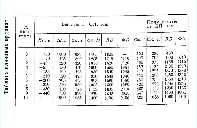
When laying out a theoretical drawing in full size, small inaccuracies may be revealed. It is likely that the plasma ordinates, after matching the projections, may differ from the tabulated ones by approximately ±3 mm. On the plaza layout, it is necessary to draw the most important structural elements of the hull - the stem, keel, sternpost, knob and starboard, bulkheads (taking into account the thickness of the plywood).
Start manufacturing the hull by assembling the bookmark (keel with stems) and bulkheads. These units are usually assembled using templates taken from the plaza or directly on the plaza. The stem is hewn out of timber with a cross-section of 200 X X 225. If there is no timber of such a cross-section, you will have to take boards or bars of smaller sizes and glue them out required package.
As a last resort, if there is no glue, all the components of the package must be riveted together with rivets d = 5 -:- 6 mm with a pitch of no more than 150 mm. The minimum design height of the keel is 200 mm. Its remaining dimensions are obtained by connecting the inner edge of the keel in a straight line from the minimum sections at the ends. When assembling the keel, it is important to ensure high quality locks - connections of its individual components. In this case, it is usually only allowed to lengthen the acceleration - the length of the lock without changing the other dimensions specified in the drawing. The parts of the keel themselves, as well as the stem, can be composite (glued).
You can make glued and the entire bookmark as a whole. The stem is glued from boards up to 15 mm thick; the keel is made from two-inch boards; in this case, there is no need to steam the workpieces for bending along the tsulag. The keel and stem can be connected “on the mustache” by gluing with a joint spread of at least 2 m. In this case, it will be possible to do without a button. When assembling the bookmark, a starboard is immediately installed on it.
When assembling transverse bulkheads, trim and flora are installed on plywood sheets cut according to the plaza data. On the bulkheads 1/2, 6 and 9 the trim should protrude behind the contour of the bulkhead by the size of the small one, which should also be removed from the plaza. At a height of 1500 mm from the OL of the vessel, shergens made of slats with a section of 50X75 are nailed to all bulkheads on the side free from the trim.
Cutouts are immediately cut in the bulkheads for the passage of the longitudinal frame. The subtlety is such that it is better to make these cutouts slightly smaller in size (in the light) than the sections of the set beams themselves; this will ensure a tight fit in place - during final assembly of the case.
First, the stowage, bulkheads and transom are placed on the slipway, then the fenders, bilges and bulwarks are adjusted and installed. The entire longitudinal set and the filling are connected to the bulkhead piping with M10 bolts. Now templates are removed from the exposed set for cutting sheets of plating for the bottom and bilge belts, sides and bulwarks.

The sheets of each belt are pre-joined by gluing “on the mustache” with a length of the bevel of at least 12 thicknesses of plywood. If the joining is performed on a backing strip (with or without glue), the width of the strip, usually cut from the same plywood as the sheets being joined, must be at least 25 thicknesses.
When gluing back plywood, the surfaces to be joined must be cleaned until the bakelite varnish is completely removed, which prevents adhesion - the adhesion of glue particles. When joining plywood without using glue, the joint must be riveted with copper rivets d = 3 -:- 4 mm in a checkerboard pattern with a rivet spacing and a distance between rows of no more than 50 mm and with obligatory lubrication with thick rubbed paint.
Sheathing sheets are usually cut with a small (30-50 mm) allowance, which is removed when adjusting the pre-assembled belt to the set. The sheathing belts are installed and attached to the frame, starting from the bottom and ending with the bulwarks, alternately on the right and left sides.
The casing is attached to the keel using 5 X 36 screws with a pitch of 70 mm; to other longitudinal connections - with 5X5 screws at 100 mm intervals, to tying the bulkheads with the same screws at the rate of each belt with four screws in each timber. It is better to install the sheathing with waterproof glue or thickly rubbed white.
When using whitewash, all external cheekbones must be covered with 1.5X50 copper strips on 2X40 copper nails or covered with fiberglass strips. The best option The entire body will be covered. The knyavdiged and wooden false keel are assembled separately from the body according to templates taken from the plaza. The drawing shows the assembly of these parts only on bolts coated with white.
If glue is used, the number of bolts can be reduced threefold, limiting them to the number necessary for reliable pressing of the parts to be glued. When the installation of the plating is completed, strings are stretched in the hull along the deck and roof of the cabin, indicating the DP. On the fenders and false side beams, the position of the beams is marked (taking into account their thickness); Shelves are installed along the fenders.

The beams are cut out according to templates from the plaza, and the position of the DP must be marked on them. At the ends, the height of the beams should be reduced to 50 mm. An allowance of about 10 mm is usually given along the upper edge of the beam, and 50 mm at the ends. It is somewhat difficult to insert the ends of the beams into the support beams.
Usually they start by placing the beam blanks in their places, but in an inverted position, making sure that the DP mark on the beam exactly coincides with the string. The position of the inner edge of the longitudinal support beams is marked on the upper edge of each beam (which in this position will be at the bottom).
Then the beams are removed. From the existing scratches, preliminary markings of the length of the mortise parts are made, which should be equal to 60 mm along the bulwarks and 40 mm along the shelf. The beams are installed in place (in their normal position). A ruler is applied vertically to the inner edge of the support beam (usually this is done from the side where the edge of the beam is shorter), and the beam is moved so that the ruler coincides with the position mark of the beam edge on the upper edge.
Now, using a ruler on the beam, draw a line on the inner edge of the insert and cut the ends of the beam according to the markings. Using a compass, the dimensions of the tenons at the ends of the beams (the height and length of the tenon and the thickness of the beam) are transferred to the corresponding places of the support beams; According to the markings, cuts are made and nests are hollowed out with the expectation of final adjustment when installing the beam.
The ends of the beams are secured in the sockets with 5 X 45 screws. All cutouts for hatches in the deck are made with Carlings and half-beams, which cut into the support beams in the same way as the beams. According to the drawing, all horizontal deck brackets, pillars and cushions are installed, which are fastened with M8 through bolts to the beams and longitudinal frame.
When the below-deck set is installed, cut out the deck sheets and fasten them with 5 X 45 screws along the contour with 70 mm spacing in a checkerboard pattern, and along the beams with 200 mm spacing. The individual decking sheets are joined in the same way as sheathing sheets.
The development and appearance of such an unusual project on the pages of the collection is due to the widespread interest of sailing enthusiasts in maritime antiquities. A small and shallow-draft (draft 1.5 m), but quite seaworthy cruising yacht, designed for long-distance voyages with a crew of 8-9 people, is given some features characteristic of sailing ships of the 18th - early 19th centuries - the heyday of the sailing fleet. At the same time, the project provides for the use of modern materials and hull design, as well as technological techniques used today.
The project does not have any specific prototype, but when developing the theoretical drawing, the contours of small and fast North American schooners were taken as a basis. As for the sailing armament, the Starina can be equipped with one of two options - a brigantine (schooner-brig) or a schooner.
The brigantines of the past were distinguished by good speed on full courses, tacking satisfactorily and, giving a wide opportunity to vary the sails, were convenient when sailing with a small crew.
The attractive aspects of the second option - schooners - are higher tacking qualities, ease of sail control, and lower weight of the spar and rigging than that of a brigantine. However, at full speed, schooners are clearly inferior to brigantines in speed.
Any of these options can be implemented without fundamental alterations to the hull and spar: the mast columns, bowsprit and their standing rigging are exactly the same.
Basic data of the yacht
When developing the general layout of the yacht, the goal was to provide the comfort necessary on long voyages. There are nine sleeping places in two salons; the yacht is equipped with a galley and latrine, auxiliary premises and sufficient volumes for storing supplies.
Strong bulkheads divide the vessel into six compartments. The forepeak, due to the small volume of the sharp bow, is used only as a chain box, where the anchor ropes of both anchors are folded. You can get here through a hole located in the bow salon closet, and the compartment is ventilated through hawse doors.
The bow salon - the cockpit - turned out to be quite spacious: its length is 2.45 m; the passage between the sofas is 1.1 m wide at the stern and 0.3 m wide at the foremast. The height to the ceiling is 1.60 m. There are two wardrobes and two sofas with soft backs, which, if hung on hinges from the side, can easily be converted into additional beds. The length of all these four bunks is at least 1900 mm with a width from 550 mm (at the head) to 400 (at the legs). Thus, four people can rest in the bow cockpit.
It is better to make the table removable here by hanging it from the mast. At the bulkhead shp. 1/2 between the cabinet and the sides there are two built-in shelves. The lower ones can be used to store books or install a small-sized receiver, the upper ones are a continuation of the hanging bunks. The cockpit is illuminated through the transparent cover of the entrance hatch and portholes in the bulkheads, and ventilated through the blinds of the entrance hood cover and bollard fans located on the sides.
Compartment between sp. 4 and 6 (hold) is intended for installing a stationary engine, placing batteries, storing sails, cables and other ship property. Here, on the starboard side, a buffet and a compartment for gas cylinders are fenced off. You can get into the hold through a hatch located on the starboard side. To reduce the size of the gangway, you can install a ladder bracket on the buffet fence. The hold is illuminated and ventilated through the entrance hatch, closed with a lattice lid.
Galley compartment located between shp. 6 and 7, includes three rooms separated by longitudinal bulkheads. On the starboard side there is a galley with dimensions of 600 mm in length and 900 mm in width of the vessel. The height of the ceiling here is 1.60 m. A galley table made of plywood covered with linoleum or plastic is permanently attached to the side of this room. The length of the compartment allows for a small dishwasher to be built into this table, which can be closed while cooking with a lid - a sliding sheet of plastic.
Above the table there is a two-burner gas stove in a gimbal suspension. The stove is connected to gas cylinders located behind the bulkhead on the shp. 6, with a flexible hose (it should not limit the swinging of the tiles in the suspension).
There are 6 pieces in the bulkhead. a window was cut into the buffet, the upper part of which, closed with sliding doors made of plexiglass, plastic or plywood, is intended for storing dishes. There are built-in food drawers below.
In the bulkhead on the shp. 7, it is also worth making a closing window 250X300 mm, which will serve to transfer cooked food directly from the galley to the aft salon. You can hang a dish dryer from the same bulkhead. Natural lighting of the galley is provided through a porthole in the bulkhead on the shp. 6. Ventilation is carried out through an exhaust fan-bollard.
On the left side there is a fenced-off latrine, equipped with a toilet pumped by a diaphragm pump installed under the floor and operated by a pedal. The latrine has dimensions 600X850 with a room height of 1.50 m.
The length of the aft cabin is 1.85 m with a passage width of 400-500 mm. The height at the entrance is 1.55 m. There are two sofas here. The lifting folding table, when lowered, tightly closes the cutout in the U-shaped sofa on the starboard side, turning it into a double bunk with a width of 1.15 m at the head and 0.40 m at the feet.
In the afterpeak bulkhead on the shank. 9½ cutouts were made in the upper side corners, giving access to the afterpeak side niches. At the mid-height of the bulkhead, along the sides of the cabinet, there are windows into the space under the cockpit, closed with sliding sashes.
The aft saloon is ventilated through bollard exhaust fans; fresh air flow - from the blinds of the stern hood embedded board through the vestibule. Light enters the salon through windows located on the sides of the vessel.
The cockpit, located at the transom, has a length of 0.75 m and a width of 1.40 m. There are seats for the helmsman on the side sections of the deck, but it will be convenient to operate the helm while standing.
The hull structure is designed to accommodate the use of bakelized or aircraft grade plywood for sheathing. It should be noted that of all brands of back plywood, only FBS plywood according to GOST 11539-65 can be considered completely waterproof. The fact is that the most common FBV brand back plywood is made with water-soluble resins and is therefore inferior. It should be noted that BS-1 grade aircraft plywood according to GOST 102-49 is also less water resistant than FBS plywood.
The body set is designed according to a longitudinal-transverse system. Powerful longitudinal braces (oak keel, zygomatic and fender beams) rest on strong plywood bulkheads; there are no frames as such.
The cross-sections of the beams of the set, the thickness of the skin and the dimensions of other parts of the body are indicated in the specification for the structural drawing. The material for making the kit parts is indicated as desirable. With any replacement, it should be taken into account that the cross-section of the parts must also be changed depending on the volumetric weight of the material actually used. In all cases, the specified value must not be violated:
γF = const
where γ is the volumetric weight of wood, g/cm 3 ;
F - cross-sectional area, cm 2.
For example, to make a keel, you were unable to obtain the oak or ash beams specified in the drawing (the volumetric weight of these materials is the same and equal to 0.72 g/cm3). It is necessary to use pine, the volumetric weight of which is 0.56 g/cm 3 . The cross-section of an oak keel is on average 20X20 cm, so it is:
γF = 0.72 400 = 288
It follows that the cross-sectional area of the pine keel should be:
F 1 = 288/0.56 = 514.3 cm 2
Keeping the cross-sectional shape of the keel unchanged (square), we obtain the thickness and height of the pine keel equal to:
α = √F 1 = √514.3 = 22.7 cm 3
In principle, when changing the dimensions of the sections of parts, it is desirable first of all to increase the vertical dimensions that increase the moment of inertia of the connection (of course, if the design of the unit or other conditions allows this).
The housing assembly technology is designed to simplify it as much as possible.
When laying out a theoretical drawing in full size, small inaccuracies may be revealed. It is likely that the plasma ordinates, after matching the projections, may differ from the tabulated ones by approximately ±3 mm. On the plaza layout, it is necessary to draw the most important structural elements of the hull - the stem, keel, sternpost, button and starboard, bulkheads (taking into account the thickness of the plywood).
Start manufacturing the hull by assembling the bookmark (keel with stems) and bulkheads. These units are usually assembled using templates taken from the plaza or directly on the plaza.
The stem is hewn out of timber with a section of 200X225. If there is no timber of such a cross-section, you will have to take boards or bars of smaller sizes and glue the required package out of them. As a last resort, if there is no glue, all components of the package must be riveted together with rivets d=5÷6 mm with a pitch of no more than 150 mm.
The minimum design height of the keel is 200 mm. Its remaining dimensions are obtained by connecting the inner edge of the keel in a straight line from the minimum sections at the ends. When assembling the keel, it is important to ensure high quality of the locks - the connections of its individual components. In this case, it is usually only allowed to lengthen the acceleration - the length of the lock without changing the other dimensions specified in the drawing. The parts of the keel themselves, as well as the stem, can be composite (glued).
You can make glued and the entire bookmark as a whole. The stem is glued from boards up to 15 mm thick, the keel is made from two-inch boards; in this case, there is no need to steam the workpieces for bending along the tsulag.
The keel and stem can be connected “on the mustache” by gluing with a joint spread of at least 2 m. In this case, it will be possible to do without a button. When assembling the bookmark, a starboard is immediately installed on it.
When assembling transverse bulkheads, trim and flora are installed on plywood sheets cut according to the plaza data. On the bulkheads 1/2, 6 and 9 the trim should protrude beyond the contour of the bulkhead by the size of the small piece, which should also be removed from the plaza. At a height of 1500 mm from 0/1 of the vessel, shergens from slats with a section of 50X75 are nailed to all bulkheads on the side free from the trim. Cutouts are immediately cut in the bulkheads for the passage of the longitudinal frame. The subtlety is such that it is better to make these cutouts slightly smaller in size (in the light) than the sections of the set beams themselves; this will ensure a tight fit in place - during final assembly of the case.
First, the stowage, bulkheads and transom are placed on the slipway, then the fenders, bilges and bulwarks are adjusted and installed. The entire longitudinal set and the filling are connected to the bulkhead piping with M10 bolts.
Now templates are removed from the exposed set for cutting sheets of plating for the bottom and bilge belts, sides and bulwarks. The sheets of each belt are pre-joined by gluing “on the mustache” with a length of the bevel of at least 12 thicknesses of plywood. If the joining is performed on a backing strip (with or without glue), the width of the strip, usually cut from the same plywood as the sheets being joined, must be at least 25 thicknesses.
When gluing back plywood, the surfaces to be joined must be cleaned until the bakelite varnish is completely removed, which prevents adhesion - the adhesion of glue particles. When joining plywood without using glue, the joint must be riveted with copper rivets d=3÷4 mm in a checkerboard pattern with a rivet pitch and a distance between rows of no more than 50 mm and with obligatory lubrication with thick paint.
Sheathing sheets are usually cut with a small (30-50 mm) allowance, which is removed when adjusting the pre-assembled belt to the set. The sheathing belts are installed and attached to the frame, starting from the bottom and ending with the bulwarks, alternately on the right and left sides. The casing is attached to the keel using 5X36 screws with a pitch of 70 mm; to other longitudinal connections - with 5X45 screws at 100 mm intervals, to the bulkheads - with the same screws at the rate of four screws for each belt in each timber.
It is better to install the sheathing with waterproof glue or thickly rubbed white. When using whitewash, all external cheekbones must be covered with 1.5X50 copper strips on 2X40 copper nails or covered with fiberglass strips. The best option would be to cover the entire body.
The knyavdiged and wooden false keel are assembled separately from the body according to templates taken from the plaza. The drawing shows the assembly of these parts only on bolts coated with white. If glue is used, the number of bolts can be reduced threefold, limiting them to the number necessary for reliable pressing of the parts to be glued.
When the installation of the plating is completed, strings are stretched in the hull along the deck and roof of the cabin, indicating the DP. On the fenders and bulwarks, the position of the beams is marked (taking into account their thickness); Shelves are installed along the fenders. The beams are cut out according to templates from the plaza, and the position of the DP must be marked on them. At the ends, the height of the beams should be reduced to 50 mm. An allowance of about 10 mm is usually given along the top edge of the beam, and 50 mm at the ends.
It is somewhat difficult to insert the ends of the beams into the support beams. Usually they start by placing the beam blanks in their places, but in an inverted position, making sure that the DP mark on the beam exactly coincides with the string. The position of the inner edge of the longitudinal support beams is marked on the upper edge of each beam (which in this position will be at the bottom). Then the beams are removed. From the existing scratches, preliminary markings of the length of the mortise parts are made, which should be equal to 60 mm along the bulwarks and 40 mm along the shelf. The beams are installed in place (in their normal position). A ruler is applied vertically to the inner edge of the support beam (usually this is done from the side where the edge of the beam is shorter), and the beam is moved so that the ruler coincides with the position mark of the beam edge on the upper edge. Now, using a ruler on the beam, draw a line on the inner edge of the insert and cut the ends of the beam according to the markings.
Using a compass, the dimensions of the tenons at the ends of the beams (the height and length of the tenon and the thickness of the beam) are transferred to the corresponding places of the support beams; According to the markings, cuts are made and nests are hollowed out with the expectation of final adjustment when installing the beam. The ends of the beams are secured in the sockets with 5X45 screws.
All cutouts for hatches in the deck are made with carlengs and half-beams, which cut into the support beams in the same way as the beams.
According to the drawing, all horizontal deck brackets, pillars and cushions are installed, which are fastened with M8 through bolts to the beams and longitudinal frame.
When the below-deck set is installed, cut out the deck sheets and fasten them with 5X45 screws along the contour with 70 mm increments in a checkerboard pattern, and along the beams with 200 mm increments. The individual decking sheets are joined in the same way as sheathing sheets.
Equipment and weapons
The internal equipment of the housing begins with the installation of partitions. Their position is preliminarily marked and coamings are installed; then, using the templates removed from the site, the fences themselves are made and installed, fastened to the coamings. Templates for partitions, like templates for making flooring for sofas and floorboards, are best made in the form of a light frame. A small strip of plywood is drawn - adjusted along the contour, temporarily secured in place and firmly connected to each other with slats.Then various reinforcements, frames for cabinets, sofas, etc. are placed and covered with plywood. The next stage is the installation of facing strips and lining of cutouts. These decorative details are best made from species such as ash or mahogany.
For ease of use, floor panels are usually made of several panels. So, in the bow cabin, it is advisable to make them from four parts with joints in the DP along the entire length of the passage and transverse ones in the middle of the cabin. What these floors should be - lattice or solid - we will let the builder decide.
We will not dwell in detail on the manufacture of sliding hatches and embedded panels, since this issue has been repeatedly covered in the pages of the collection. Let us only remind you that embedded panels must be made taking into account ensuring good ventilation interior spaces. To reduce the possibility of splashes entering through louvers in vertical coamings and walls, the horizontal slats of the grille should be angled with their top edges inward to deflect splashes outward.
As already noted, it is best to cover the entire exterior of the body (and the cheekbones are obligatory) with fiberglass cloth on epoxy or polyester resin. As a last resort, if it was not possible to obtain fiberglass, the cheekbones should be covered with a protective copper strip. In any case, to improve the adhesion of bakelized plywood to adhesives or dyes, the surfaces of the body must be sanded. It is most advisable to use dyes based on epoxy compounds: they are durable, do not lose color, and are easily washed off from dirt. You can also use pentaphthalic or oil enamels; in this case, it is better to cover the underwater part of the hull and the hold with red lead. For painting the underwater part, antifouling paints of the NIVK type are recommended.
Now about the ship's armament. The vessel's mast was designed taking into account the main features of shipbuilding from the times of the sailing fleet: the “classical” proportions and principles of armament were preserved. In the old days, the masts of small ships were most often made in one piece or assembled from well-fitted parts - pieces held together from the outside with vulings (tied with a strong cable) every 800-1000 mm. The rest of the spar was usually made in one piece. Of course, these days it is easier for a builder to ensure the required high quality of masts and large yards if he makes them glued.
The armament of the vessel begins with the installation of a bowsprit; it is securely fastened into the nedgeds and then laced to the cutout in the upper part of the nedgeded, as shown in the sketch.
Then the mast columns are installed and immediately secured with cables. Usually vangs are applied in the following order. The inner pair of shrouds on the starboard side goes around the top of the mast, resting on the rounded cushions of the salinga - calva, and is fastened with benzel; a fire forms around the mast. Then the inner pair of the left oort, the outer right and the outer left are superimposed. Soft turnbuckles are inserted into the deadeyes, and the shrouds are somewhat tightened.
A forestay is placed on the foremast over the shrouds. To prevent the fire from becoming tight, moussing is done on the forestay. The forestay is covered with a system of blocks on the bowsprit, after which the end of the forestay is laid behind the cleat on the bow of the vessel.
The mainstay is wound in the same way; its lower end ends with a block through which the guard stay passes.
The staystay goes around the foremast on both sides, is then carried through the outlet blocks installed on the deck, and is secured to the cleats on the forecastle.
It should be emphasized that the wiring of the forestays was described in relation to armament with a brigantine. On schooners, the forestay is brought out to the bowsprit foot, and the mainstay passes through a block attached to the top of the foremast, then along the foremast down to the outlet block fixed on the deck, and is stuffed with hoists on the deck.
After posting the stays, the final tightening of the standing rigging begins. The forestay and stern shrouds of the foremast are covered first. This requires gradualism and thoroughness; it is important that the mast is not tilted towards any of the sides, and that its longitudinal tilt towards the stern is no more than 2° for a brigantine and up to 5° for a schooner. When the forestay and stern shrouds are stuffed, they tighten the shrouds of the right and left sides in pairs, going from bow to stern.
The mainmast is secured in the same way; its inclination towards the stern should be 3° for a brigantine and exactly the same as that of the foremast for a schooner.
Shades are applied to the covered shrouds - the first row is at the level of the bulwark, and the rest after about 400 mm. On the outer shrouds the lining is secured with a sliding bayonet, the two middle ones are covered by a bleaching unit. At the top, where the distance between the cables is less than 100 mm, the castings can be fastened through the cable, i.e., pass first, for example, the right middle cable, then the left one, etc.
In advance, before the topmast is raised, the puttens shrouds are installed, connecting the main shrouds with the main shrouds. The puttens shroud is passed into a slot lined with a copper strip on the spreader leg, goes around the shroud with a pile applied to it, and is attached to the shroud with benzels. The pile applied to all the shrouds at once is a metal rod or, less commonly, a rope covered with a heel.
The topmasts are lifted separately using a tackle called a topstall. The root end of the topmast is laid behind the hook on the right side of the ezelgoft, put on the top of the mast, passed through a pulley, set obliquely in the spur of the raised topmast, goes up again - to the block on the left side of the ezelgoft and the running end is lowered to the deck. Raised all the way by its wide (90X90 square) part into the round cutout of the ezelgoft, the topmast is stopped from lowering by a scaffolding bar, which is inserted into the scaffolding slot at the spur of the topmast and rests with its ends on the long-saling.
The main shrouds are superimposed by the ends on the chicks at the top of the topmast in pairs, like the main shrouds on the masts, and are covered with soft turnbuckles, based between the deadeyes at the lower ends of the main shrouds and the upper ends of the shrouds. The brigantine's forestay is fitted through blocks on the bowsprit's toe, with the running end of the hoists being secured to a cleat on the forecastle. The mainstay is passed through a block on the rear side of the mast in the saling area, goes down along the mast and is attached to dowel strips. Simultaneously with the wall-stays, forduns are stuffed with lanyards on the channel, which are put on by the lights over the wall-stays. Let us note in passing that all the deadeyes of the main shrouds and forduns are made smaller than the deadeyes of the main shrouds.
When rigging a yacht with a schooner, a shortened “dry” fore topmast is installed, which does not carry any gear and is used only for hoisting signal signs and flags. On the top of it you will need to attach several small blocks for signal halyards. The ezelgoft of the foremast must have a hole of a smaller diameter (∅60 mm).
Now about the rigging for lifting the yards. The foresail for lifting the foresail is based between blocks, one of which is fixed under the saling, and the other in the center of the foresail. The root end of the tackle is attached to the pendant of the block on the mast, and the running gear goes from the stern to the bow through the block on the yard, then from bow to stern through a block on the mast and attached to the deck.
The fore-mars-yard is raised by the fore-mars-drayrep, which is attached to the middle of the yard, passes through the block on the topmast and ends with a block of the fore-mars-halyard splashed into the drirep.
The fore-tops-halyard is based on the mantle, and its root end is attached to the left channel, and the running end is attached to the lower deadeye on the right.
The dimensions of the yards themselves are indicated in the drawing; they have round cross sections and taper from the middle to the ends along the curve of a circular segment. In the middle of the yards, fastening strips are installed, which prevent the raks-yokes and blocks from moving to the sides.
The raks yoke is a cable on which wooden balls are placed - raks, which play the role of bearings when the yard moves relative to the mast. The root end of the raks-yoke cable is attached to the yard, and the running gear goes around the mast, passes through the block on the yard and is attached to the dowel strips in front of the mast. This wiring makes it possible to tightly pull the raised yard into place to the mast and vice versa - to loosen the yoke when lowering or raising the yard. The running end of the mars-yard yoke is attached to the eyeliner of the shroud.
The finished fore-yard is equipped with per-tami - cables that run at a distance of about 750 mm along the yard and are designed for movement along them when taking reefs and cleaning sails. The sagging middle parts of the perths are supported by vertical supports. On the topsail yard, feathers are not necessary, since a light yardarm is easy to lower and raise again.
The horizontal position of the yards is ensured by topenants. The fore-yard toppings are attached to the pendants of the blocks under the eselgoft, are guided into the blocks on the ends of the yard, and again through the blocks under the eselgoft they are pulled to the deck, where they are attached to the dowel strips. Topenants of the mars-ray are put on the toes of the rey. pass through blocks on the topmast and are attached to the deck.
The pendants of the braces are put on the ends of the yards, and blocks are splashed into the free ends; the length of the fore-braces pendants is about 1000 mm, and the fore-mars-braces are about 500 mm. The main ends of the foresail braces are attached to the top of the mainmast, the running ends of the foresail braces pass through the blocks of pendants on the yard legs, then through the blocks attached half-bayonet to the mainstay (slightly below the fastening of the main ends) and down to the deck. Fore-topsail braces represent one end, which with its middle is superimposed on the top of the main topmast on top of the rigging (secured with a bleached knot); its running ends are carried out to the deck through blocks of pendants and a pair of blocks on the mainstay.
The gaff and boom are based on the mainmast. The gaff rises up the mast using a gaff-gardel. which is fixed at the heel of the heel, threaded through the block under the saling and attached at the bottom on dowel strips.
The second gear of the gaff - the dirik-halyard - is used to tighten the luff of the mainsail with the gaff. Dirik-fal can be carried out in several ways. The simplest is wiring in one lopar. A spruit is attached to the gaff (from the toe to a point located at 1/2 of the length of the gaff from the heel), passed through a block at the end of the dirk halyard; the running end of the dirk halyard is passed through the block under the ezelgoft and lowered onto the deck.
You can carry out a dirik-fal in three laps. In this case, the root end of the dirik-halyard is secured to the end of the gaff. The running end is pulled through a two-pulley block under the ezelgoft, again goes to the middle of the gaff, passed through the block, again goes to the two-pulley block under the ezelgoft and after it is attached to the deck.
The main sheet rests between the blocks on the boom and the blocks on the transom gunwale of several laps.
Rax yokes are also placed on the gaff and boom lashes.
When a vessel is rigged with a schooner, the gaff and boom are mounted on the foremast in the same way as on the mainmast.
Let's now move on to sewing and rigging the sails. It is best to use filter fabric type sailing fabric. Each panel must be stitched with false stitches for greater strength. Along the luffs, the sails are lined with lyctross, into which the required number of krengels are splashed.
Reef bows are sewn onto the foresail on both sides - reinforcing strips of fabric 50 mm wide with eyelets for the passage of reef seasons. If a number of reef bows with reef seasons are made on the foresail, reef pendants are attached to the side luffs at the level of the reef bows, which are carried to the deck through blocks on the toes and blocks attached to the forestay light. When taking reefs, the sail is pulled to the yard with reef pendants, after which the tying of the sails begins.
It is not worth installing reef bows on the topsail, since the sail area is small and it will be difficult to take reefs on it.
The same grommets as on reef bows are made along the upper luffs of straight sails for attaching to the yards with a snowflake, along the upper, fore and lower luffs of gaff sails for attaching to the gaff, mast and boom. Rakes are installed along the luffs of staysails and jibs. The distance between the eyelets and frames should be about 300-350 mm everywhere. The drawing shows eyelets made from an overlock ring with a flared tube. If possible, standard eyelets and staysail carabiners should be used (instead of homemade wire stays).
Blocks of sheets and gypsum are attached to the lower clew corners of straight sails. The root end of the gitov is attached to the yard at a distance of 1.4 m from the middle for the foresail and 1.0 m for the topsail. The running end is passed through a block in the clew, through a block on the yard (attached 0.6 m closer to the middle of the yard than the point of attachment of the main end), passes through the shroud-clutch - a guide clip fixed to the shroud, and ends on the lower eyeliner this guy.
The foresail sheet of each side is attached to a ring on the outside of the bulwark (in front of the mainsail), pulled through a block in the clew corner of the sail, returns back and passes through a pulley-hat in the side to the inside of the bulwark, where it is laid behind the clew at the gunwale.
Fore-topsails, laid behind the corners of the sail, pass through the blocks on the toes of the fore-yard, then through the blocks at the middle of the same yard and down to the deck in front of the mast. On small sailing ships, blocks of some other gear were often used to guide the topsail sheets; for example, the top of the sheet passed into the larger pulley, and the foresail into the smaller pulley.
For pulling the side luff to the wind, the fore-bowlini are carried from the spruit on the sail to the bow of the vessel, where they are directed to the cleat using rosin blocks.
Fore-mars-bowlini pass through blocks on the fore-stay, fixed at the level of the top of the mast, then through blocks on the bowsprit, which are installed between the fore- and fore-stay, and are laid behind the cleats on the bow of the vessel.
The bull- and knock-tails, with which the softness of the sail is pulled up - to the yard, are laid behind the fenders on the lower and side luffs, respectively, pass through blocks suspended from the yard, onto blocks fixed under the saling - for the foresail or on the forestay - for the topsail , and then mounted on dowel strips in front of the mast.
We will not dwell on the running rigging of gaff sails and staysails - this equipment is familiar to sailing enthusiasts. Let us only add that since the beginning of the last century, gaff weapons have changed very little.
When rigging a vessel, it is best to use a self-factor cable for running rigging parts and hemp cables for standing rigging. Nylon cables can only be used for running rigging; shrouds and stays cannot be made from them, as they stretch and lose strength.
Here are the recommended diameters of standing rigging cables (mm): fore and main stays, stays and props - 25; main stays, stay stays - 13; mainstay and waterstay - 19; lashings and lashings - 10; vulings and lanyards of shrouds - 6; wall shrouds and fore-duns - 8.
Diameters of running rigging and sail trim cables (mm): bowlines, gitovs, rax yokes, topenants, topsail braces - 6; gardeli and drairep - 13; braces, topsail halyard, topsail sheets - 8; sheets, pendants, jib, liktros - 10; gordeni and bowlini - 1÷6.